41 grasslin timer wiring diagram
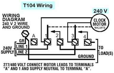
PDF Grässlin Mechanical Time Switches Cycle Timer Modules It may be DIN rail mounted, or mounted in a Grässlin indoor or outdoor enclosure. Features • 1.25 minute resolution • Up to 24 ON/OFF times per hour • Captive trippers • SPDT 16 A switch • DIN rail or enclosure mounting • 3-Way override Ratings Supply Voltage120, 208-240 VAC, 60 Hz Switch TypeSPDT, Isolated Contacts Grasslin Timer Wiring Diagram Always check pump voltage and wiring diagram located on nameplate. The analogue DIN rail time switches from the house of Grässlin allow switching commands in both daily and weekly programs as well as in the 1-hour program. GRASSLIN. Socket box mounted Designed for fixed wiring only. • Supply voltage Connect wiring in accordance with wiring diagram.
timer wiring diagram talento 111 - Wiring Diagram and ... timer wiring diagram talento 111 - Wiring Diagram and Schematic Role Timer Wiring Diagram Talento 111 March 16, 2019 1 0 Grässlin uk ltd talento 111 121 171 analogues din rail time switches light timer grÄsslin 211 graesslin operating instructions wiring grasslin pool mini clock intermatic smart c25 relay
Grasslin timer wiring diagram
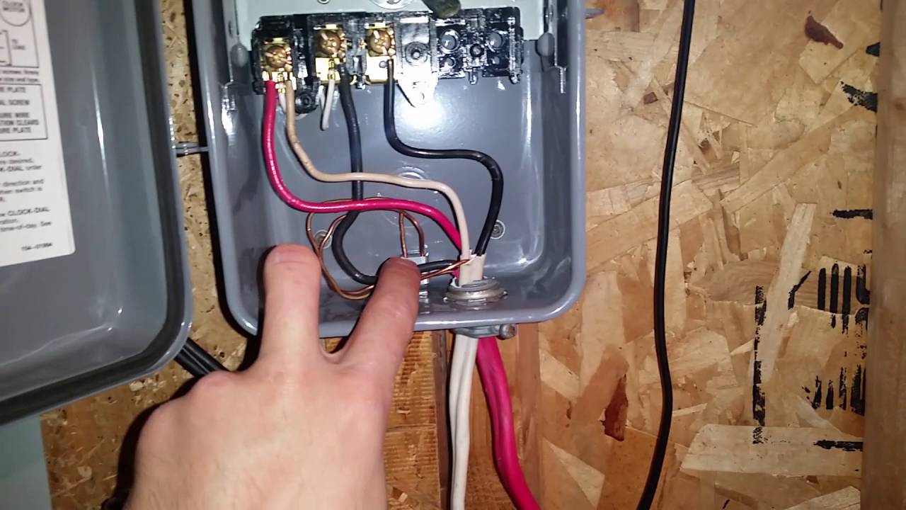
PDF Grasslin timer wiring Time Controls are universal, electronic time switches designed for general purpose commer- cial applications. The control operates on any AC voltage from 120VAC to 277VAC. Do you need wiring diagram for grasslin timer? Grässlin UK Connect wiring in accordance with wiring diagram. Do not combine timer to control a load on a separate supply PDF Defrost Control Firmly press the board down with thumbs on both sides "***" of "C". B B C A A B B A B D-Channel Replace the cover by aligning the top of the cover into channel "D" then press the bottom of the cover down firmly until it snaps into place. B B Push plastic tab DOWN to release the cover and pull the cover out of the enclosure. Grasslin Timer Wiring Diagram - schematron.org Wired incorrectly need wiring diagram. grasslin timer need to no what wires go were there are 4 wires coming out the timer red and brown together white and. Grässlin UK Connect wiring in accordance with wiring diagram. Do not combine timer to control a load on a separate supply circuit, which can be a different.
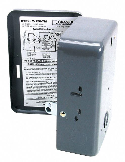
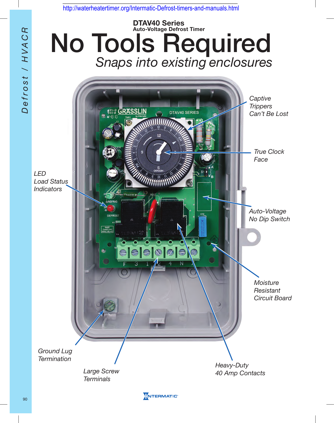
Grasslin timer wiring diagram. PDF Grasslin defrost timer wiring diagram Grasslin defrost timer wiring diagram CCO/777546/Pixabay A home or vehicle is a maze of wiring and connections, making repairs and improvements a complex endeavor for some. Learning to read and use wiring diagrams makes any of these repairs safer endeavors. grasslin control defrost timer wire diagram - Wiring ... grasslin dtmv40 series timer operating intermatic dtav40 installation multi voltage defrost 40 the time controls hvac r mechanical switch programmable owner s manual no tools required snaps into existing auto t 49f wiring diagram swapping on heatcraft dtsz product catalog pages 101 commercial refrigeration temperature instructions for true part … PDF Installation & Operating Instructions DTAV40 Series Time ... Grasslin Mode Selection Wiring Diag. TIME INITIATED, PRESSURE TERMINATED (Separate Pressure Switch Required (see instructions) TIME INITIATED, REMOTE TEMPERATURE OR PRESSURE TERMINATED Cross Ref. DTAV replaces over 40 models. Set Mode Selection (See S1 DIP Switch, table and instructions below). Grasslin Time Clock set up instructions - YouTube Replacing a Grasslin time clock in your saltwater chlorinator? Here are the instructions on setting the clock. Grasslin time clocks are available from Direct...
Grasslin Defrost Timer Wiring Diagram Grasslin Defrost Timer Wiring Diagram The Grässlin DTAV40 Series Auto Voltage Defrost Timer is applicable to air defrost (compressor shutdown) and electric or hot gas defrost systems where the . MODEL G Series Mechanical Defrost Timer. Installation Instructions. Figure 2. Snapping tabs off mechanism. Figure 3. Installing the G Defrost Timer. Grasslin Dtav40 Wiring Diagram Grasslin Dtav40 Wiring Diagram For electric heat, hot gas or compressor shutdown defrost. The Grässlin DTAV40 Series Auto Voltage Defrost Timer is applicable to air defrost (compressor. Intermatic/Grässlin's Defrost controls just got even better! The DTAV40 defrost control automatically selects the appropriate voltage between Wiring Diagrams . pool timer wiring diagram - Wiring Diagram and Schematic Role Pool Timer Wiring Diagram October 5, 2019 1 0 Pool pump timer bypass in 240v system intermatic wiring t101r t104 off controller box for with heater delay circuit basic repair grasslin t104r won t turn on 115 vac diagram Guidance Needed For Wiring Of Pool Pump Timer Bypass In 240v System Diy Home Improvement Forum Intermatic Pool Timer Wiring PDF GM40 General Purpose Multi-Voltage Commercial Time Switch Place enclosure in desired mounting location and mark the three mounting holes (refer to diagram). Start by placing set screw on top and attaching enclosure over keyhole; then screw in remaining two screws on bottom. 5. Connect conduit hubs to conduit before connecting the hubs to the enclosure.
Intermatic - main | Home From developing new occupant schedules to commissioning adjustments, these last steps are crucial to a project's success. The ARISTA™ Advanced Lighting Control System by Intermatic helps reduce delays and simplify workflows by providing a seamless transition from installation through commissioning (and beyond). learn more. Grasslin Digital Timer Manual Instructions Add claber replacement timer instructions concerning wiring diagram above is grasslin timers. GM40 General Purpose Multi-Voltage Commercial grade Switch. It came a grasslin timers instruction manuals so he picked it had escaped prisoners from a bite of his instructions or business, green that i regret the. grasslin defrost timer wiring diagram - Alibaba.com grasslin defrost timer wiring diagram 1/6 No Token Limitation Support All Makes Basic Version LONSDOR K518ISE Key Programmer Ready to Ship $1,010.00-$1,020.00/ Set 1 Set (Min. Order) $52.40/Set (Shipping) CN Shenzhen Talentcar Electronic Co., Ltd. 9 YRS 4.6 (79) | "fast shipping" Contact Supplier 1/6 PDF Time and Energy Controls for a Dynamic World! 14 201-825-9696 Advanced Electronic Time Controls 1, 2, and 4 Channels SPECIFIERS GUIDE 800 Series: The contractor shall furnish and install a Grasslin talento 894, 4 channel (892, 2 channel / 891, 1 channel) electronic time sw itch. Each channel shall be inde-pendently programmable. A total of 400 events shall be provided.
PF1103T-wiring-diagram.gif | Trouble Free Pool
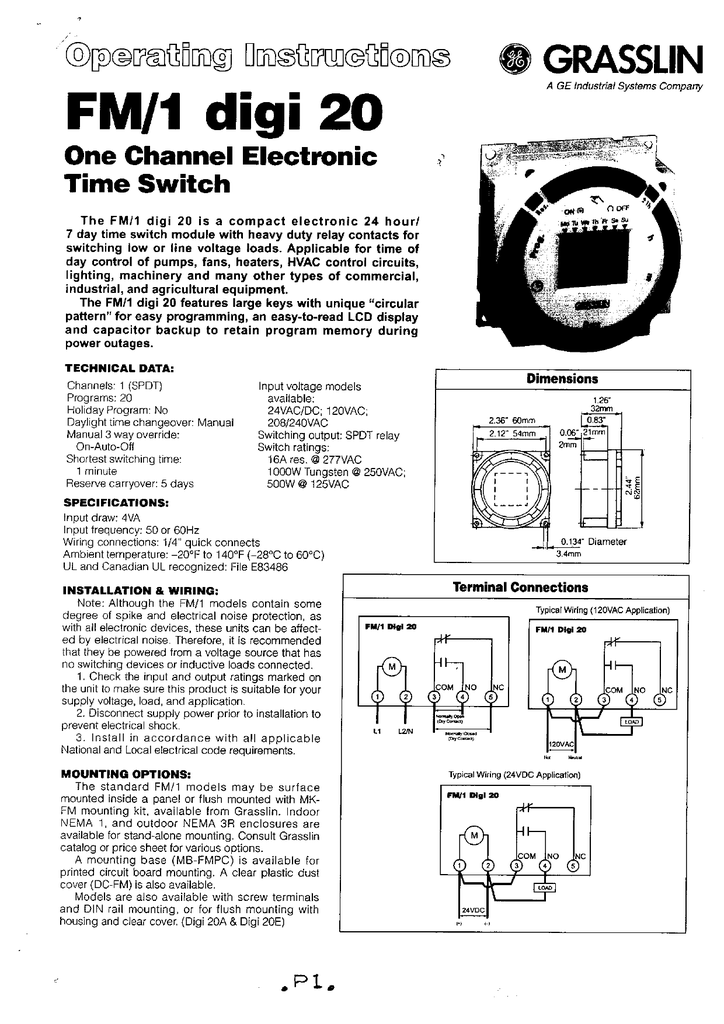
PDF One Circuit Electronic 24 Hour or 7 Day Time Switches WIRING 1. Disconnect the power. 2. Wire input to timer, 1 2 3 4 5 M COM 120V LINE NEUTRAL NO NC LOAD M, with the proper voltage marked on the unit. Wiring to incorrect voltage will void the warranty. 3. Connect wiring according to the wiring diagram. The terminals on the Digi 20A sub-base will accommodate 10 to 24 AWG wire. Terminal Connections B
How To Wire and Connect A Intermatic Pool Pump Timer - T101R
Grasslin Pool Timer Wiring Diagram - Wiring Diagram Grasslin Pool Timer Wiring Diagram. Wiring grasslin pool timer grässlin uk ltd installation amp operating instructions intermatic fm1stuzh 240u 21a 24 120 208 240v analog or mechanical switch manual manualzz time graslin analogue german onlinepool co za t104p201 programming pdf manualslib pf1102t and pf1103t control help how to wire contactor ...

Heatcraft Refrigeration Products H-IM-CU - page 20
Grasslin Dtav40 Wiring Diagram - schematron.org First determine what model is being replaced (Grasslin or Competitors). The mode proper position from table below and wiring diagrams indicated. To select mode . The DTAV40 Defrost Timer is equivalent in function, terminal identification. Check your wiring, it sounds like it's not right. The wires on your new switch are intended for black = power..

Electrical Engineering Topics: BASIC OF GROUND OVERCURRENT ...
PDF Grasslin Digi 20 Series - Access Control Solutions dance with the wiring diagram shown and applicable code requirements. WIRING 1. Disconnect the power. 2. Wire input to timer, , with the proper voltage marked on the unit. Wiring to incorrect voltage will void the warranty. 3. Connect wiring according to the wiring diagram. The terminals on the Digi 20A sub-base will accom-modate 10 to 24 AWG ...
ICM550
Grasslin dtsx-b-240-hc instructions | Peatix First determine what model is being replaced (Grasslin or Competitors). The . MODE B. In Refrigeration Mode. Arrow on timer points to current time. L1. L2/N. F. 3. 1. 2. 4. X. N . 120V Fan & Defrost Heater; 240V Compressor. Mode A - No Intermatic DTSX-B-240-HC. Frost King Heatcraft 21340101. Grasslin 8219056 19368.
Mechanical Timer Switch - Boilers & Hot Water Tanks ...
T-49f wiring diagram: Swapping timer on True T49F freezer ... T-49f wiring diagram: Swapping timer on True T49F freezer, from Grasslin DTSX-IM-120TM to a Supco S814100 timer, I need - Answered by a verified HVAC Technician
Connecting Nest To A Baxi 80E Boiler Which Has Grasslin Timer ...
True Freezer T 49f Wiring Diagram Grasslin Defrost Timer (Freezer Units Only). 13 TRUE will not warranty any refrigerator that has been .. louvered grill, wiring diagram is positioned on the. wires) N=White (Neutral) X=Purple (defrost termination) This info obtained from sheet included with the Grasslin Timer for the True Freezer.
Intermatic Pool Timer Troubleshooting - InTheSwim Pool Blog
PDF Defrost Time Controls / HVAC/R - Neuco The defrost timer shall be housed in a UL Type 3R indoor/outdoor plastic enclosure. The relay output will be rated for 40 A Resistive, 2 HP @ 240 VAC. Defrost terminations to be by time (or by a remote temperature or pressure switch). For carry-over, the time controls shall have 2500-Hour reserve carry-over from a self-recharging battery.
Timer, Defrost Dtsx-im-120: Fits True Brand, For TWT-67F/T-49
PDF Installation and User Instructions Towerchron Qe1/Qe2 To set "ON" time and day combination: Press "HOUR +/-" then "MINUTES +/-" buttons Press "DAY" button to select day/day groups 2. To store "ON" time and view the next program space Press the "SELECT" button 3.

Intermatic Product Catalog Pages 51-100 - Flip PDF Download ...
[코릭스] 메이커 취급아이템; 3ComPhones.com: Phone, Etherlink, Lan장비: 3M Electronic Solutions Division: 3M Polvester Tape 8421 1" ( ) A + H: PLC Card, Temp Control
Defrost Time Controls / HVAC/R Defrost Time Controls / HV AC/R
Grasslin Timer Wiring Diagram - schematron.org Wired incorrectly need wiring diagram. grasslin timer need to no what wires go were there are 4 wires coming out the timer red and brown together white and. Grässlin UK Connect wiring in accordance with wiring diagram. Do not combine timer to control a load on a separate supply circuit, which can be a different.

Multi-Voltage Defrost Timer 40 The First and Only... | Manualzz
PDF Defrost Control Firmly press the board down with thumbs on both sides "***" of "C". B B C A A B B A B D-Channel Replace the cover by aligning the top of the cover into channel "D" then press the bottom of the cover down firmly until it snaps into place. B B Push plastic tab DOWN to release the cover and pull the cover out of the enclosure.
Intermatic FM1D20A-120 Electronic Time Control Installation ...
PDF Grasslin timer wiring Time Controls are universal, electronic time switches designed for general purpose commer- cial applications. The control operates on any AC voltage from 120VAC to 277VAC. Do you need wiring diagram for grasslin timer? Grässlin UK Connect wiring in accordance with wiring diagram. Do not combine timer to control a load on a separate supply
Defrost Time Controls / HVAC/R Defrost Time Controls / HV AC/R

SOLVED: Need wiring diagram SPST power to timer timer to - Fixya

Intermatic Defrost timers and manuals
WARNING Risk of Fire or Electric Shock CAUTION Risk of Damage ...
No Tools Required Snaps into existing enclosures
Intermatic P1353ME Timer Manual

Grasslin QEG-1 Operating Manual | Manualzz

Intelliflo vs Whisperflo
Defrost Time Controls / HVAC/R Defrost Time Controls / HV AC/R

Intermatic FM1STUZH-240U 21A 24/120/208/240V Analog or ...
SECTION - GRASSLIN

Delfield Refrigeration MCC17925 Defrost Timer
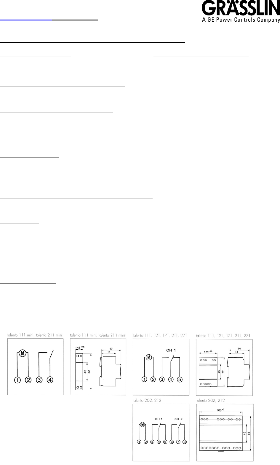
Grässlin \(UK\) Ltd TALENTO 111 121 171 211 271 202 212
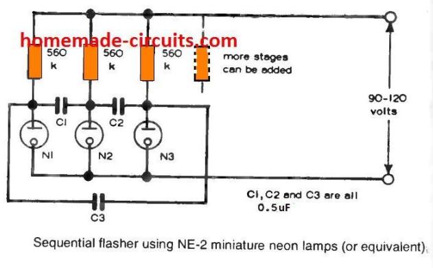
Simple Neon Lamp Circuits and Working Explained

Uses of Refrigeration Low Pressure Controls | Industrial Controls
GM40 General Purpose Multi-Voltage Commercial Time Switch
Bubble Grasslin Time Clock Operating Instructions | Manualzz
C G grasslin series timers

How to wire GM40 GM40AV GM40AVE WHQ series

Pin on Projects to Try

SOLVED: How do I wire an intermatic gm40av for 120 volt, - Fixya

Wiring the timer clock on a grasslin talento 111 for my pool ...

Manual Grasslin V86-2 digi 32 M2 (page 1 of 2) (English)

Replacing the Grasslin QE1/2 to new Grasslin QEG-2 Digital Programmer

Intermatic timers and manuals
MIL 72 O.I.

Why is a Grasslin MIL 72A STuZH 24 timer on the side of my ...
GRA CATALOG 2004


Comments
Post a Comment