42 top level block diagram
Block Diagrams - SourceForge The Top Level Block Diagram does not look very interesting. from left to right. The Input block does not indicate where the input data is coming from. The Process block only indicates that some processing is taking place on the input data but again there is no indication as to what processing is taking place. Block diagram of radio - BrainKart Block diagram of an FM (frequency modulated) transmitter is given on Pic.2.4. Information being transferred, i.e. the modulating signal, is a signal from some LF source. it is being amplified in LF amplifier and then led into the HF oscillator, where the carrier signal is being created. The carrier is a HF voltage of constant amplitude, whose ...
PDF Chapter 2: The Systems Engineering (SE) Process - NASA system (top level), subsystem, or component (bottom level) requirements. Requirements are often expressed as "shall" statements. "The Thrust Vector Controller shall provide vehicle control about ... as a hierarchy of major subsystems on a block diagram (e.g., an

Top level block diagram
Block diagram of television transmitter - BrainKart Block diagram of television transmitter. The basic television Broadcast transmitter block diagram is shown in figure (a). The block diagram can be broadly divided into two separate section, viz., one that - Generates an electronic signal (called video signal) corresponding to the actual picture and then uses this video signal to modulate an R-F carrier so as to be applied to the transmitting ... vhdl - In Vivado, how to instantiate a user defined "Block ... I've imported my VHDL code into a user defined Block Design, and I exported my I/O interfaces from this block design, now I need to instantiate this Block Design in the top level Block Design that contains the Xilinx Zynq Arm core and AXI interconnect. When I right click on the Top-level Block Diagram, I see two choices: "Add Module" "Add IP" Functional flow block diagram - Wikipedia A functional flow block diagram (FFBD) is a multi-tier, time-sequenced, step-by-step flow diagram of a system's functional flow. The term "functional" in this context is different from its use in functional programming or in mathematics, where pairing "functional" with "flow" would be ambiguous. Here, "functional flow" pertains to the sequencing of operations, with "flow" arrows expressing ...
Top level block diagram. Top Level Block Diagram of The Heart Conductive System BLOCK DIAGRAM OF HEART CONDUCTIVE SYSTEM. INTRODUCTION. Historically, the neural elements of the heart have been labeled the conductive system by the histological and medical community. At the academic and technological levels, it is important to recognize the system employs techniques more sophisticated than implied by the term conductive. Top Level Block Diagram Top Level Block Diagram Main Block Diagram code This is the LabVIEW block diagram of the entire program. Well, not quite the whole program, but this is the top layer of the many software modules that make up the program (over 100). PDF System Level Block Diagram for Autonomous Vehicle Hardware System Level Block Diagram Figure 1 - Hardware System Level Block Diagram Each hardware subsystem can be seen in the Hardware System Level Block Diagram above in Figure 1. This block diagram shows all of the inputs and outputs of each subsystem and how they relate to the overall system. Each of the subsystems is discussed in more ... simulation - Realizing Top Level Entity in Testbench using ... I'm a newbie in VHDL and hardware world. I'm trying to make a Count&Compare example using Top Level Hierarchy and test it with testbench and see the results on ISIM. Here is my block diagram sketch: So I end up these 3 vhd source files: Counter.vhd
Pyramid Diagram | Types of Flowcharts | IDEF0 Visio | Top ... Use the libraries from the Block Diagrams solution to draw block diagrams for your business documents, presentations and websites in a few minutes. Data Flow Diagram Data flow diagram (DFD) is the part of the SSADM method (Structured Systems Analysis and Design Methodology), intended for analysis and information systems projection. 2.2 Draw the top-level block diagram of a Priority | Chegg.com 2.2 Draw the top-level block diagram of a Priority Encoder with an 8-bit input, and a 3-bit output, a one-bit validation, and with left arbitration. Label the inputs and label the outputs on the diagram correctly based on the textbook and the lecture. Create a truth table with the following description. System Block Diagrams - Rice University A system block diagram is a high level modularization of the system that separates the overall system into maximally decoupled sub-systems. System block diagrams enable one to visualize the system as large interacting LabVIEW Block Diagram Explained - NI In this introduction to the Block Diagram, we examine the concept of this tool as well as the Block Diagram's relationship with the Front Panel. We also explore how to open the Block Diagram, how to find objects in the Functions palette and put them on the Block Diagram, and how to use different toolbar icons. In addition, we learn how to build a simple block diagram to illustrate the ...
PDF Fpga Design Having a HDL top level source ile allows user edits without it being overwritten by Vivado tools when the block diagram is updated. Add a new top level VHDL ile to the project and open the cpu_system block diagram. Remove the BRAM and make the BRAM port signals external. This exposes the BRAM interface to the top level. PDF Block Diagrams - A Quick Overview Typically, though, the hardware block diagram occurs first. As with other diagrams, the initial version may abstract away most details and focus on the major physical blocks of functionality and the signal flow between or among such blocks. Structure The high-level structure of a block diagram expresses signal I/O and flow. Inputs are Block diagram - Wikipedia A block diagram is a diagram of a system in which the principal parts or functions are represented by blocks connected by lines that show the relationships of the blocks. They are heavily used in engineering in hardware design, electronic design, software design, and process flow diagrams.. Block diagrams are typically used for higher level, less detailed descriptions that are intended to ... Top-level context diagram | Pyramid Diagram | Block ... From this diagram lower-level diagrams are generated." [IDEF0. Wikipedia] The IDEF0 diagram example "Top-level context diagram" was created using the ConceptDraw PRO diagramming and vector drawing software extended with the IDEF0 Diagrams solution from the Software Development area of ConceptDraw Solution Park. Top Level Diagram

EDGE
PDF Intense PC2 Top Level Block Diagram - fit-PC Intense PC2 - Top Level Block Diagram e SO-DIMM 204-pin slot_A DDR3L SDRAM (8GB DDR3-1333/1600) Intel 4th Gen Core i7/5/3/ Celeron mobile processor (Haswell ULT) Dual core 64-bit i7-4600U; i5-4300U;

Home Background Project Designer: Roberto Mancera Texas ...
2.3 Draw the top-level block diagram of a 4-bit | Chegg.com 2.3 Draw the top-level block diagram of a 4-bit Adder/Subtractor that supports 2's compliment and negative integers with an error bit. Label the inputs and label the outputs on the diagram correctly based on the textbook and the lecture. Create a truth table with the following description.

The diagram below shows a top-level block-diagram of | Chegg.com
Block Diagram File with Parameters - Generate VHDL File ... Hello, please tell me if i got something wrong in my workflow: 1. My Top-Level File is a BDF (Block Diagram File) 2. I placed VHDL Blocks including Generics which are seen as parameters in the BDF. There i can set a parameter e.g: parameter value type COUNT_MAX 1000 Signed Integ...
NI 5442 Block Diagram - NI Signal Generator Documentation
Top-level block diagram of the IP surveillance camera ... Download scientific diagram | Top-level block diagram of the IP surveillance camera controller reference design. from publication: FPGA design of a camera control system for road traffic ...
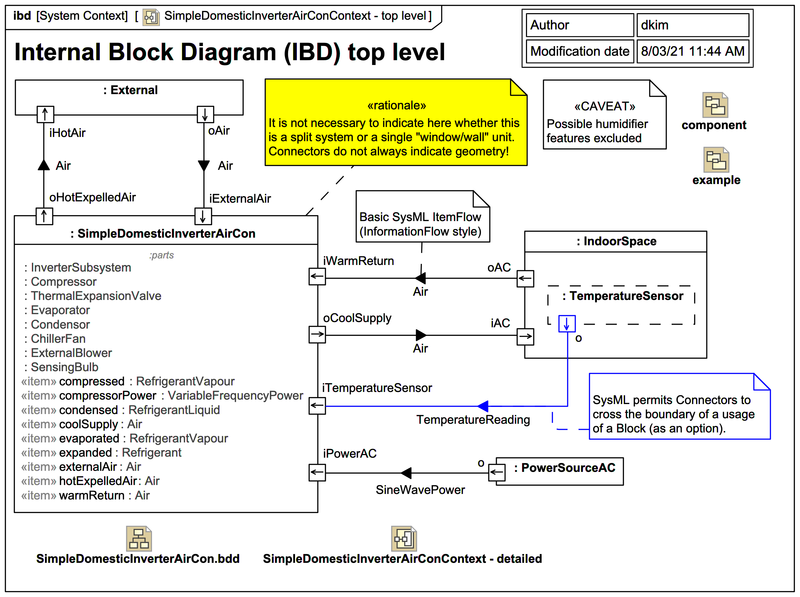
SysML Internal Block Diagram | Webel IT Australia
Block Diagram Maker | Lucidchart A block diagram is a specialized flowchart typically used by engineers to provide a visualization of systems and their various interactions. Block diagrams are ideal for creating a high-level overview of a system to account for major system components, visualize inputs and outputs, and understand working relationships within your system.

Block Diagram - Learn about Block Diagrams, See Examples
Top-Level Block Diagram - Pseudo nMOS Array Multiplier Top-Level Block Diagram. Top-Level Block Diagram (Detailed) Like this:

Block Diagram - Learn about Block Diagrams, See Examples
Why do I need to run "Create HDL Wrapper..." In Vivado IP integrator a block diagram must be wrapped in an HDL wrapper. Why? From Designing IP Subsystems Using IP Integrator on p149 Xilinx provides this answer: "The top-level HDL wrapper around the block design is needed because a BD (block design) source cannot be synthesized directly."
Top Level User Designed Hardware Block Diagram, HD Png ...
Block Diagram Maker | Free Online App - SmartDraw A block diagram is a specialized flowchart used in engineering to visualize a system at a high level. SmartDraw helps you make block diagrams easily with built-in automation and block diagram templates. As you add shapes, they will connect and remain connected even if you need to move or delete items.

FullChip physical block diagram | RTLery
PPT Space Systems Engineering - Home Each block in the first/top level diagram can be expanded to a series of functions in the second level diagram, and so on (see example, next slide). Lines connecting functions indicate function flow and not lapsed time or intermediate activity. Diagrams are laid out so that the flow direction is generally from left to right.

Asic top level in one week - case study | RTLery
57654 - Vivado - Setting top level HDL Wrapper of a block ... The top level wrapper of a module should never be set to OOC. The proper way to set a block diagram to OOC is to set the .bd under the top level HDL wrapper to be OOC.
High-level block diagram of the system. | Download Scientific ...
Labview: Null Window ... stopped at unknown on the block ... The top-level VI ".vi" stopped at unknown on the block diagram of ".vi". I apologise for having to blank out the vi names but i cannot give vi names, say what the software is used for or give over code. I can say that it uses NI USB 6212 IO cards, interfaces with Rhode and Swartz instruments and uses alot of file IO.
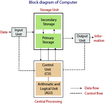
Block Diagram of Computer
Proposed Top Level Block Diagram | Download Scientific Diagram Download scientific diagram | Proposed Top Level Block Diagram from publication: Blood pressure measurement using Korotkoff sounds | Blood pressure and heart rate measurement are the most commonly ...

Top-level block diagram of the ESS processor. | Download ...
Functional flow block diagram - Wikipedia A functional flow block diagram (FFBD) is a multi-tier, time-sequenced, step-by-step flow diagram of a system's functional flow. The term "functional" in this context is different from its use in functional programming or in mathematics, where pairing "functional" with "flow" would be ambiguous. Here, "functional flow" pertains to the sequencing of operations, with "flow" arrows expressing ...

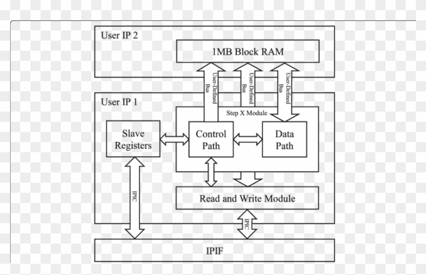
Weighted Round-Robin Scheduling Module in Reprogrammable Hardware
vhdl - In Vivado, how to instantiate a user defined "Block ... I've imported my VHDL code into a user defined Block Design, and I exported my I/O interfaces from this block design, now I need to instantiate this Block Design in the top level Block Design that contains the Xilinx Zynq Arm core and AXI interconnect. When I right click on the Top-level Block Diagram, I see two choices: "Add Module" "Add IP"

Top level block diagram of the proposed architecture ...
Block diagram of television transmitter - BrainKart Block diagram of television transmitter. The basic television Broadcast transmitter block diagram is shown in figure (a). The block diagram can be broadly divided into two separate section, viz., one that - Generates an electronic signal (called video signal) corresponding to the actual picture and then uses this video signal to modulate an R-F carrier so as to be applied to the transmitting ...

fit-PC2 Block Diagram | Manualzz
Top Level User Designed Hardware Block Diagram, HD Png ...

Top level Block Diagram of the Proposed solution | Download ...

Trigger matched firmware Top Level block diagram 4ch 3.2gbps ...
NI PCI-5421 Block Diagram - NI Signal Generator Documentation

StarVision PRO - Quick Start Video #26 Visualize RTL Designs from Top Level to Block Diagram View

3.1-1 Top level block diagram of the olfactory and oskonatory ...

PXI-5610 Block Diagram - NI RF Signal Generators Help (NI ...
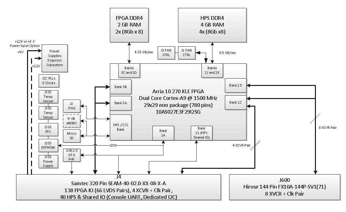
MitySOM-A10S Architecture - MitySOM-A10S Altera Arria 10 ...
Top-level block diagram | Details | Hackaday.io

can-newsletter.org - Semiconductors
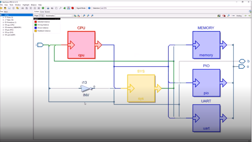
StarVision PRO - Quickstart Video #26 Visualize RTL Designs ...
Visualizing Top Level to Block Diagram View in RTL designs ...
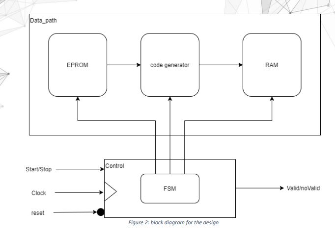
Solved Data_path EPROM code generator RAM Start/Stop Control ...
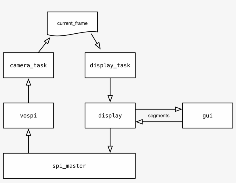
The High-level System Block Diagram For The Firmware ...
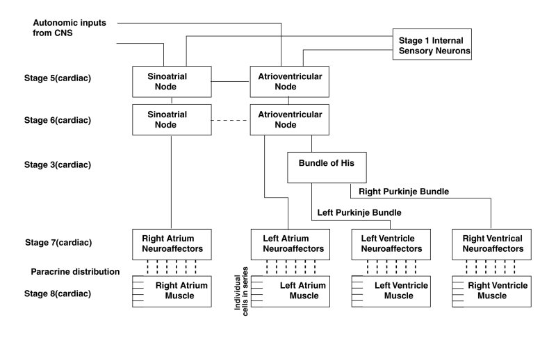
TOP LEVEL BLOCK DIAGRAM OF THE HEART CONDUCTIVE SYSTEM

SBC-FLT (i option) – Top Level Block Diagram - fit-PC | Manualzz

Top-level block diagram of the system | Download Scientific ...

Figure 1. Top Level Block Diagram of the VCO SYSTEM

Top level block diagram of measurement system. | Download ...

Top-level block diagram of the system | Download Scientific ...

Functional flow block diagram - Wikipedia
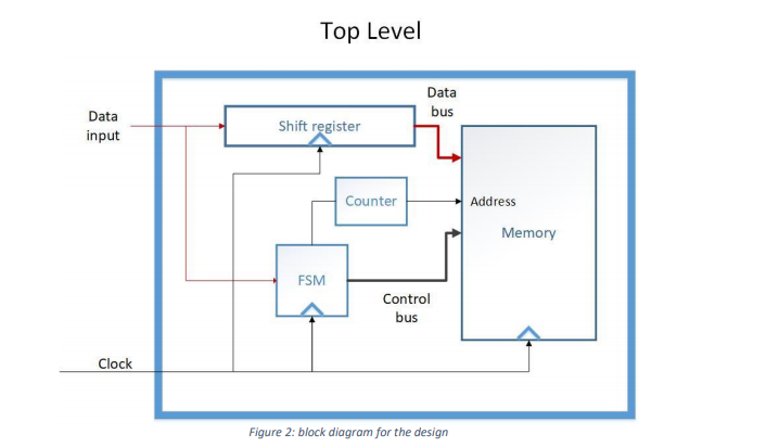
Solved Top Level Data bus Data input Shift register Counter ...

Block Diagram - NI Signal Generators Help (NI-FGEN 18.1 ...
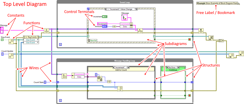
Block Diagram - LabVIEW Wiki
Block diagram - Wikipedia
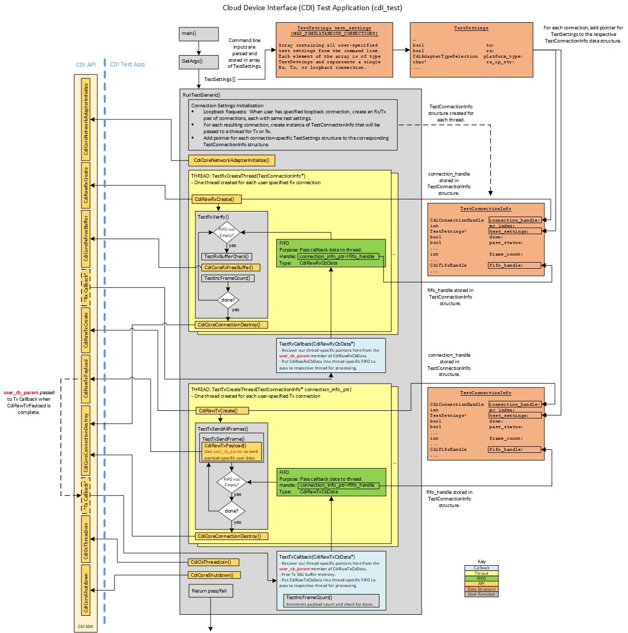
CDI SDK: CDI Test


Comments
Post a Comment