43 oil tank piping diagram
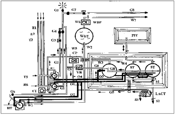
PDF Project Guide - Marine | Lubrication Oil System Internal fuel oil system Fuel oil diagram Specification for heavy fuel oil (HFO) Specification for marine diesel oil (MDO) Specification for gas oil / diesel oil (MGO) Diesel oil Heavy fuel oil Heated pipe with insulation. Duplex full flow filter. Main engine. Fuel oil drain tank To HFO service or settling tank. PDF nanual book 100sl w/s 1-19 The diesel oil supply pipes should be provided with strainers to avoid any blocking of the pipes. The pump on the primary burner is also provided with strainers built in the pumps. For supply and return pipe for oil sludge between the incinerator and the waste oil tank, See pipe diagram (Final drawing).
Single and Double Fuel Tank Piping Diagram — Heating Help: The Wall the diagram that Alan posts is.... proper code but as a on going argument,( here on the wall) I much prefer to fill each tank w/ its own fill and then twin up the vent. The crossover pipe in my opinion puts a lot of strain on that first tank.... especially 10-20 years down the road where the tank may be weaker...
Oil tank piping diagram
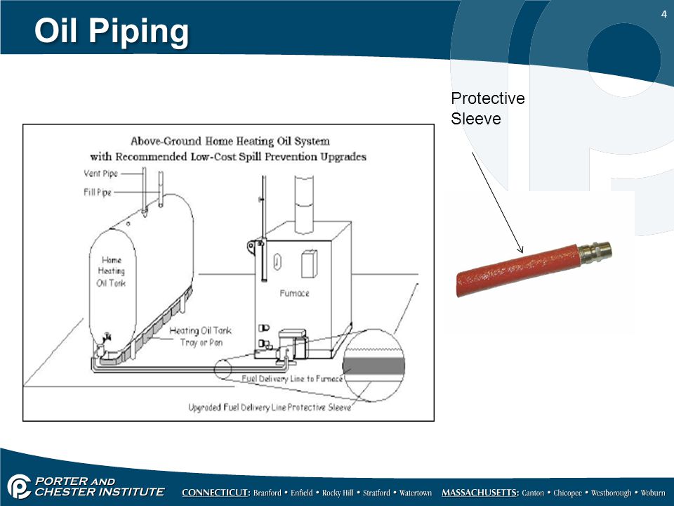
33 Oil Tank Piping Diagram - Wiring Diagram Database Oil tanks and piping chapter 3 chapter 3oil tanks and piping 3 3 introduction the comfort cleanliness and efficiency of todays oilheat systems rely on clean uncontaminated fuel The tank piping and valves for appliances burning oil shall be installed in accordance with the requirements of this chapter. Basics of P&ID (piping and instrumentation diagram) | Instrumentation... Calibration procedures, Instrumentation, Electrical,Interview question, Instrumentation job opportunities,Piping & Instrument diagram symbols,Flow transmitter calibration, DP type transmitter calibration,Control valve calibration,Flow measurement,Level measurement, Temperature... Volatile Organic Compound During the loading of oil tankers, the inert gas tank atmosphere (which is infused with residual VOC) has to be displaced. It can be displaced to the atmosphere, to an onboard VOC control method or to an onshore VECS piping diagram. • Vapour recovery system or other VOC control system drawings.
Oil tank piping diagram. Piping Arrangement - Conventional Oil Tanker Basics Piping Arrangement. The pipes leading from the cargo tanks to the pumps are termed as bottom lines, from the pump-room up to deck are called risers. The pipeline system illustrated above in Diagram 1 is better suited to the centre line bulkhead type of ship. Each tank or oil compartment has two... Standard Procedures for Tank Cleaning, Purging and Gas free... Tank cleaning is the process of removing hydrocarbon vapors, liquids, or residues from cargo tanks onboard a tanker. On Tankers using the inert gas systems, the Chief Officer shall carry out the operations mentioned in Article 1 and maintain the cargo tanks in a "Non-Flammable condition at all... Piping Systems Heat loss from pipes, tubes and tanks - with and without insulation - foam, fiberglass, rockwool and more. Recommended max. flow velocities on the delivery side when pumping light oils. Draw P&ID diagrams online in the browser with Google Docs. Pipes - Fractional Equivalents. PDF PowerPoint Presentation The diagram below shows a Fuel oil supply system for a large 2 stroke crosshead engine. However the set up is typical of any fuel system for a marine diesel engine operating on 2. Following the same diagram above describe the fuel oil system and the passage of fuel oil from the DB tank to the engine.
PDF I. Piping Diagrams I. PIPING DIAGRAMS. 22. Figure 6. 11. Expansion tank must be rated for use with potable water. 12. Use either indirect/tank sensor or system/pipe sensor mounted on common return to the boiler. P&ID Process Diagram, Piping, Symbol, Abbreviation, Equipment... This blog is about process diagram, piping and instrumentation diagram P&ID, standard P&ID symbol and notation. - Boiler Section; - Condensate Recovery; - Boiler Feed Water; - Cooling Water; - Raw Water; - Plant and Potable Water; - Fuel Tank; - Dry and Plant Air; - Nitrogen; - Inert Gas; - Hot Oil... Tanks, piping and valves Tanks, piping and valves. The loading lines and pipes mentioned here refer to gas carrier's cargo There is no oil lubrication of the piston itself, but there is oil in the crankcase on the compressor. Picture 13 shows a diagram of a typical rotor set with the common combination of four and six lobes. Piping and instrumentation diagram - Wikipedia A piping and instrumentation diagram (P&ID) is a detailed diagram in the process industry which shows the piping and process equipment together with the instrumentation and control devices. Superordinate to the P&ID is the process flow diagram (PFD)...
How to Read Oil and Gas P&ID Symbols | Kimray P&ID (Piping and Instrumentation Diagram) vs PFD (Process Flow Diagram). Process diagrams can be broken down into two major categories: process and Here are the symbols for pumps, tanks, and other types of equipment. The most common pumps used in oil and gas industry are screw... PDF KEMEL COMPACT Seal | OILING Oil Level in #2/3 tank Adjust the oil level, if necessary, based on the AFT draft to keep the pressure balance shown below TEST ORDER (Typical Piping Diagram - Deviations from actual diagram exist.) LEAK TEST PROCEDURE in dry-dock (KEMEL COMPACT Seal Type CX with #2/3 Oil Line). PDF Instrument | Piping and Connecting Shapes Piping and Instrument Diagram Standard Symbols Detailed Documentation provides a standard set of shapes & symbols for documenting P&ID and PFD Open Bulk Storage Dome Roof Tank Cone Roof Tank Internal Floating Roof Tank Double Wall Tank. Oil Burner. Fired Heater. Vertical Turbine. PDF Installation, operation and maintenance MANUAL | OIL FIRED BOILERS PIPING DIAGRAMS Diagram 10 V1 V2. From system. Expansion tank. 6. Piping used to connect the oil burner to the oil supply tank shall not be smaller than 3/8" iron pipe or 3/8". OD copper tubing.
An Engineering Guide to Modern Fuel Systems
PDF PG_M-III_L2832H | I 00 25 0 Symbols for piping Waste oil system Clean leak oil from the fuel injection valves, fuel injection pumps and high-pressure pipes, is led to the fuel leakage alarm unit, from which it is drained into the clean leak fuel oil tank. The leakage alarm unit consists of a box, with a float switch for level monitoring.
Heating Oil Piping Defects & Leaks: where heating oil leaks ...
Diagram below shows typical PID Symbols for various piping components such as reducers, spectacle blinds, sight glass, hose connections, blind flanges etc. Diagram below shows PID Legend for Vessels, Distillation Columns, Fixed Cone Roof Tanks, Floating Roof Tanks and Dome Roof Tanks.
How an Oil Tank Works - Smart Oil Gauge
oil tank piping - DoItYourself.com Community Forums Fuel oil tanks always have a bunch of gunk in the bottom. FYI: In some states, a two pipe systems with an outdoor or underground tank have been outlawed. This is in case there is a leak in the return line.
Maintenance of Fuel Oil Systems
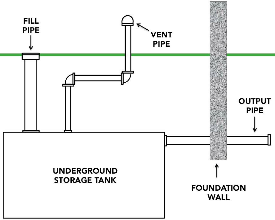
oil tank piping code requirements - Bing Oil tanks supplying oil burners used in residential and commercial heating applications are fueled by above-ground or buried oil storage tanks whose fill and vent piping is usually steel (referred to also as black iron pipe or galvanized iron pipe); in some jurisdictions non-metallic piping is permitted, though...

Marine Sea Time: FUEL OIL LINE DIAGRAM AND EXPLANATION IN SHIP
Oil Piping for Duplex or Paired Oil Storage Tanks How duplex oil storage tanks are piped for fill, vent, & oil lines Heating oil tank fill and vent pipe requirements Where should oil line fire safety valves and check valves be located? Questions & answers about how to pipe or hook up dual or duplex heating oil storage tanks.
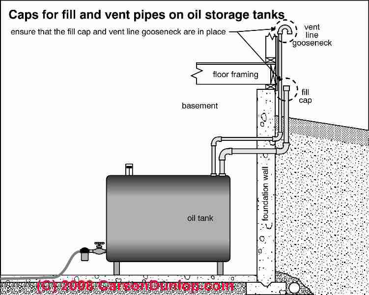
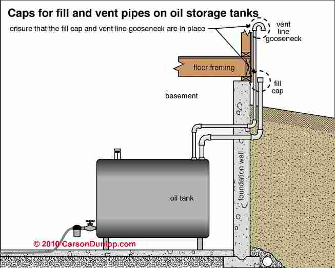
Oil Tank Fill & Vent Piping Installation & Inspection
PDF Part VI … Machinery and Piping Systems … July 2019 (SRL) .3 Diagram of ballast system; .4 Diagram of air, overflow and sounding pipes; .5 Diagram of exhaust gas system; .6 Diagrams of ventilation 1.12.2 Tanks for oil fuel, lubricating oil as well as oil used in power transmission systems, control, propulsion systems and heating systems and their pipework and...
Flow of Crude Oil Through the Tank Battery in Oil & Gas ...
Oil Tank And Piping - UTICA BOILERS... | ManualsLib UTICA BOILERS BC3D Manual Online: Oil Tank And Piping. OIL TANk AND PIPING. Component coding. Mr-ps.
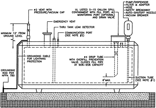
Home Heating Oil Tank Installation Guidelines
PDF Microsoft Word - Consolidated Study Material P-98.doc Supervise fuel-oil piping and storage in buildings. P-98. All liquid fuel piping and fuel-oil storage tanks shall be hydrostatically tested for tightness by the contractor who Working indicator with audible alarm attached; DIAGRAM A drain pipe shall be installed at the base of shafts...

Chapter 10: FUEL OIL TANKS PIPING | Manualzz
Piping engineering - YouTube How to Draw a P&ID (Piping and Instrumentation Diagram) - Distillation Column. CHEE470. Fundamental of Pipe (Pipeline) used in Process Piping (Basic of Industrial Pipe). TANK - Storage Tank Design as per API 650. IMAGEGRAFIX SOFTWARE.

Diagram of Stage II Vapor Recovery the UST and typically runs ...
Oil Day Tank Piping Diagram › fuel oil tank piping diagrams. 5 days ago Oil Tanks and Piping Chapter 3 Chapter 3—Oil Tanks and Piping 3-3 Introduction The comfort, cleanliness and efficiency of today's oilheat systems rely on clean, uncontaminated fuel reaching the oilburner.
Oil Tank Fill & Vent Piping Installation & Inspection
PDF Oil/Gas Pipeline Technology | 2.1.5 Tank Installation Technology Diagram of pipeline crossing. 6. Oil & Gas PiPeline TechnOlOGy. 2.1.5 Tank Installation Technology. PFM pipe end shaping machine is mainly used for processing special bevels during pipeline welding, and an auxiliary apparatus of full-automatic welding in long-distance pipeline...
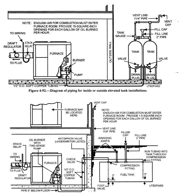
Mechanical for Oil Heat - ppt video online download
Volatile Organic Compound During the loading of oil tankers, the inert gas tank atmosphere (which is infused with residual VOC) has to be displaced. It can be displaced to the atmosphere, to an onboard VOC control method or to an onshore VECS piping diagram. • Vapour recovery system or other VOC control system drawings.
The Homeowner's Guide to Underground Oil Tank Removal ...
Basics of P&ID (piping and instrumentation diagram) | Instrumentation... Calibration procedures, Instrumentation, Electrical,Interview question, Instrumentation job opportunities,Piping & Instrument diagram symbols,Flow transmitter calibration, DP type transmitter calibration,Control valve calibration,Flow measurement,Level measurement, Temperature...
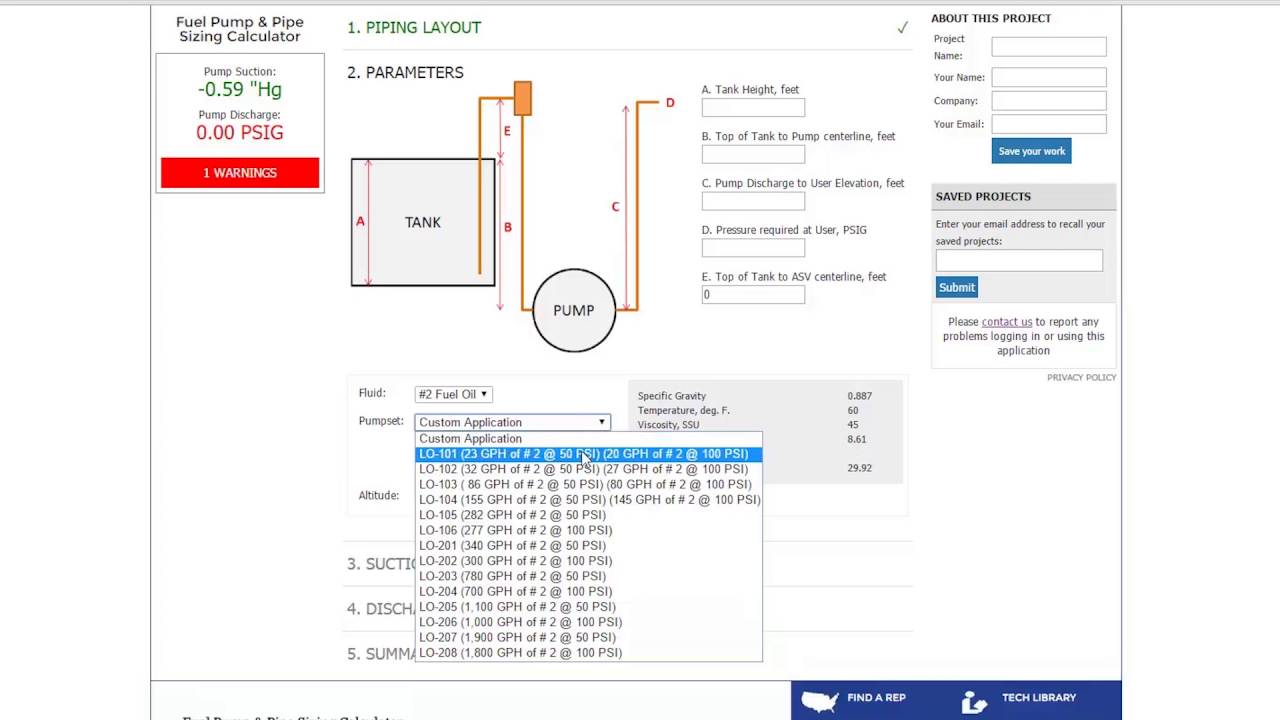
Tutorial: Fuel Oil & Pump Sizing
33 Oil Tank Piping Diagram - Wiring Diagram Database Oil tanks and piping chapter 3 chapter 3oil tanks and piping 3 3 introduction the comfort cleanliness and efficiency of todays oilheat systems rely on clean uncontaminated fuel The tank piping and valves for appliances burning oil shall be installed in accordance with the requirements of this chapter.
Why doesn't my oil tank fill all the way — Heating Help: The Wall
Untitled
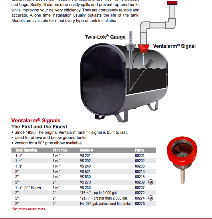
Day Tank TRS Series
An Engineering Guide to Modern Fuel Systems
Installation
Home Heating Oil Tank Guidance

Thermal Expansion Tank Design and Operation | 2014-06-02 ...

Investigating Fuel Oil Leaks and Spills – Expert Article ...

Fuel Pipe - an overview | ScienceDirect Topics

Pipe & Pump Sizing | Preferred Utilities Mfg

Roth Oil Tank Installation
An Engineering Guide to Modern Fuel Systems

Single and Double Fuel Tank Piping Diagram — Heating Help ...

Exterior, Above-Ground Oil Storage Tank - Inspection Gallery ...
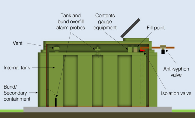
Get to Know Your Oil Storage Tank
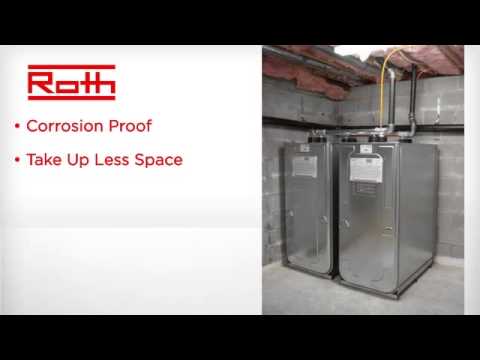
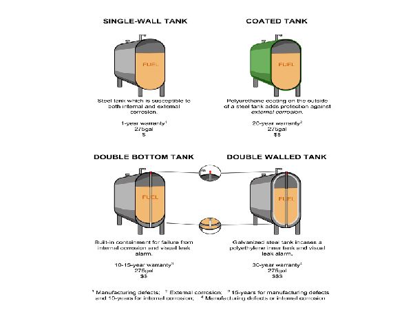
Roth Double-wall Home Heating Oil Storage Tanks
Installation
Recommended Practices for Owners of Home Heating Oil Storage ...
Roth Double-Wall Oil Storage Tank Installation Instructions
SUPERVISE FUEL-OIL PIPING AND STORAGE IN BUILDINGS
Oil Piping for Duplex or Paired Oil Storage Tanks
State of Alaska
Buildings Bulletins 2018-010 - Technical
Tanks for Solar Heating and Domestic Hot Water
Fuel Oil Systems
Heating of Fuel Oil Storage Tank - Guideline for Cargo Ships
Pitching tank fill and vent pipes — Heating Help: The Wall

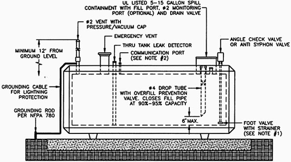
TYPICAL UNDERGROUND FUEL OIL TANK
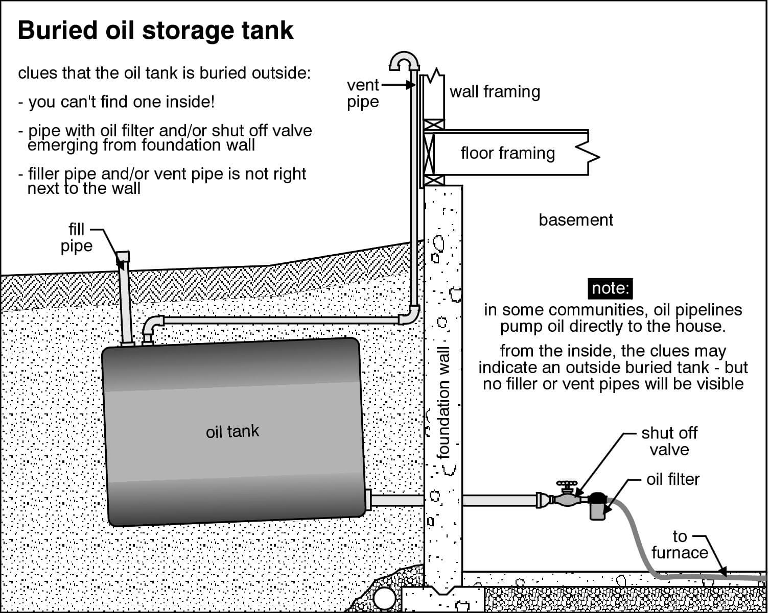
Clues to Finding Buried Fuel Oil Tanks | Star Tribune


Comments
Post a Comment