42 voltmeter wiring diagram
PDF Voltmeter — Instructions VOLTMETER — INSTRUCTIONS WIRE NUT FLAT WASHER NUT WASHER VOLTMETER GROMMET U-BRACKET DO NOT LEAVE ANY HARDWARE OUT OF THESE CONNECTIONS Diagram 1 ground source (Step 2) should be connected as shown in Diagram 1, to the voltmeter's connection post marked "-". 5. The wire from the fuse box (Step 3) should Autometer Voltmeter Wiring Diagram - easywiring Voltmeter wiring figure 5. Voltmeter instructions wire nut flat washer nut washer voltmeter grommet u bracket do not leave any hardware out of these connections diagram 1 ground source step 2 should be connected as shown in diagram 1 to the voltmeter s connection post marked. 1 16 diameter gauges mount in 2. Step 6 connect positive wire.
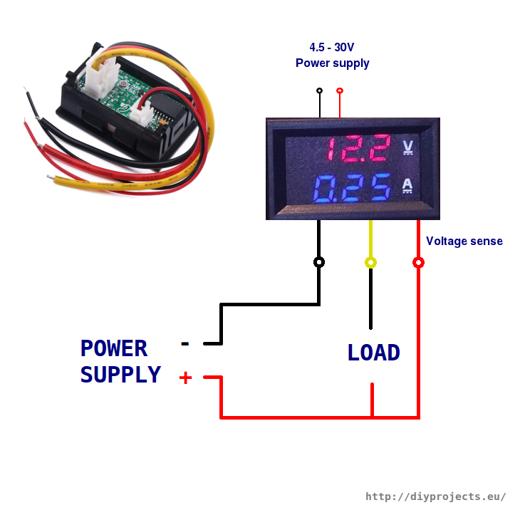
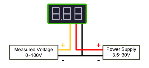
How to wire a digital Voltmeter Ammeter - Hobby electronic ... The completed wiring of the voltmeter ammeter with the power supply. Here you can see the power supply set to 12V and the project that it's connected to is using 0.12 amps. When I first tried it I thought it wasn't reading current so be aware that it will only read down to .01 of an amp so if your circuit is only using a few milliamps the ...
Voltmeter wiring diagram
Sunpro Voltmeter Wiring Diagram DIAGRAM 1. In the automotive context, a voltmeter gauge displays the number of volts stored by the vehicle's battery. Sunpro manufactures volt gauges that instead feature a. Attach one end of the wire to a clean ground source, such as a metal panel. tion posts of the voltmeter Diagram 1. 2. Voltmeter Gauge Wiring Diagram - autocardesign Voltmeter Gauge Wiring Diagram - wiring diagram is a simplified customary pictorial representation of an electrical circuit. It shows the components of the circuit as simplified shapes, and the facility and signal contacts with the devices. A wiring diagram usually gives counsel roughly the relative tilt and concurrence of devices and ... Voltmeter Wiring - Hot Rod Forum The wiring will need to be series and not parallel as a volt meter is wired, in the diagram posted earlier. The AMP gauge sits in the middle of the electrical system, monitors all loads, lights, starter .. whatever when activated. Light 15 amps starter 30 amps, and so one.
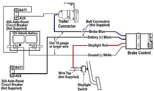
Voltmeter wiring diagram. How to Test an Anti Lock Brake System Wheel Speed Sensor 2022-02-02 · You will need to use a specific wiring diagram with a voltmeter set to ohms of resistance to check each wire from end to end. This will help detect a broken or shorted wire, once repaired it should turn the light off. This is an example of an ABS sensor wiring diagram. Conclusion . Be observant when first driving the vehicle after testing the ABS system. Listen for … Digital Voltmeter Ammeter Wiring Diagram - IOT Wiring Diagram Digital Voltmeter Ammeter Wiring Diagram. By ... Eiechip led digital voltmeter ammeter mini dc multimeter 100v 10a blue red amp dual display volt meter gauge car cur monitor tester 0 28 online in thailand b079l33vg2 โวลต ม เตอร แอมป แบบด จ ตอล จอ sho dc0 50a พร อม shunt ขนาด ... DC 100V 10A Voltmeter Ammeter Blue + Red LED Amp Dual ... Lots of good videos on Youtube describing this item but here is a simple connection tutorial. A prelude to other projects coming soon. One thing will connect... Potentiometer Connection, Circuit Diagram, Wiring Guide ... 2021-01-27 · 1. You should check the potentiometer connection to make sure that it is operating properly with a voltmeter. Then, attach the terminals of the voltmeter to the output and input terminals of the POT. Turn on the voltmeter and check the signal. Turn the knob of POT to regulate the signal. If the signal value on the voltmeter increases and ...
U0212 Lost Communication With Steering ... - OBD-Codes.com Gain access to a wiring diagram and determine where the main powers and grounds come into the SCCM. Reconnect the battery before continuing, with the SCCM still disconnected. Connect the red lead of your voltmeter to each B+ (battery voltage) supply coming into the SCCM connector and the black lead of your voltmeter to a good ground (if not sure, battery negative … Digital Volt Amp Meter Wiring Diagram - Cadician's Blog Dual Digital Display Dc Voltmeter & Ammeter 0-100V 0-100A Australia - Digital Volt Amp Meter Wiring Diagram. Wiring Diagram includes each illustrations and step-by-step instructions that might enable you to definitely really develop your venture. This can be beneficial for both the individuals and for experts who're seeking to find out ... Ammeter Circuit Diagram - U Wiring Ammeter Wiring Diagram wiring diagram is a simplified good enough pictorial representation of an electrical circuit. The completed wiring of the voltmeter ammeter with the power supply. Amp Gauge Wiring 1 Always disconnect the ground lead from the vehicle battery before wiring any gauge. The circuit diagram of multi range DC ammeter is shown in ... Voltmeter, Wiring diagram info and Gerbing Heated clothing ... Voltmeter, Wiring diagram info and Gerbing Heated clothing. Jump to Latest Follow 1 - 5 of 5 Posts. C. Citypol86 · Registered. Joined May 16, 2007 · 87 Posts . Discussion Starter · #1 · Oct 23, 2007. I just finished replacing a burned-up 3-phase regulator on my 1999 750 Monster. ...
PDF Installation Analog AC Voltmeter - Blue Sea the source. Do not connect the voltmeter in a serial (in-line) confi guration. Wiring Diagram for AC Voltmeters (Installation (continued) 4. Calibration The voltmeter is calibrated at the factory and recalibration should never be necessary. However, if adjustment does become necessary the needle may be reset to the zero mark. Vdo Voltmeter Wiring Diagram Consequently . Only connect cables according to the electrical wiring diagram. VDO has tried to answer most of your questions regarding Installation and Trouble shooting of VDO Performance Instruments. You need to Note: These Instructions are for VDO Gauges and Accessories only. Voltmeter, L Ground-. Diagram C. Proper wiring of the VDO ... Voltmeter Diagram Wiring - U Wiring Voltmeter Diagram Wiring. Amarante Pruvost. November 6, 2021. I did not touch the existing amp meter wiring. Connect the red lead of your voltmeter to each B battery voltage supply coming into the RCM module connector and the black lead of your voltmeter to a good. Pin On For Inpiration. Swapping Ford Modular Engines: Wiring Guide - DIY Ford Ford Wiring and Connectors. Using Ford factory wiring harnesses is an option for most engines and projects. However, the newer the engine and vehicle, the more difficult it is to use the factory components. When using factory computers and wiring, pay close attention to the connectors. Ford frequently changed them, even within model years. For ...
Simple Voltmeter Circuit Diagram
How to Install a Voltmeter on Your Boat - LiveAbout Be sure to get a digital model rather than an analog voltmeter, because you want the accuracy and ease of measuring very small differences in voltage. Wiring The wiring is as simple as connecting the positive (red) and negative (black) leads of the meter to the primary power input in your switch panel - assuming a standard panel.

Electric Oil Pressure Gauge Wiring | Car gauges, Oil pressure ...
Digital Ampere and Voltmeter Wiring Diagram - YouTube Digital Ampere and Voltmeter Wiring DiagramYou can Buy that DC Digital Ampere and Voltmeterhttps://amzn.to/31McekJDigital Voltmeter Ammeter Wiring DiagramDC ...

Ammeter to voltmeter wiring. | Vintage Mustang Forums
How to Wire Voltmeter Gauges on a Car - It Still Runs The voltmeter connection can be made at the battery positive and negative if desired. Use either butt connectors or the commonly supplied wire taps to connect the voltmeter wires to the wiring harness. Butt connectors are stronger and more reliable, but wire taps are faster and don't require cutting the original wire.

Step Up Step Down DC Buck Converter With Voltmeter | PCB Smoke
Ammeter Gauge Wiring Diagram - easywiring Stewart warner amp gauge wiring diagram valid voltmeter wiring diagram album diagrams wire center is just one of the many collections of sample. 18 gage wire from fuel tank to gauge. Without it you will not know there is a problem until it is too late.

wiring diagram of 2 panel voltmeter for 3 phase voltage ...
PDF VDO Voltmeter - High Performance Racing Products Diagram C Proper wiring of the VDO Voltmeter Merchandise warranted against defects in factory workmanship and rn*rials for a period of 24 months aner purchase. This warranty applies to the first retail purchaser and covers only those products exposed to normal use or service. Provisions of this warranty shall

diymore 5PCS 0.28" Digital Voltmeter Ammeter DC 100V 10A Amp ...
Voltmeter Ammeter - Electronics DIY This Voltmeter Ammeter was designed to measure output voltage of 0-70V / 0-500V with 100mV resolution and 0-10A or more current with 10mA resolution. It is a perfect addition to any DIY laboratory power supply, battery chargers and other electronic projects where voltage and current consumption must be monitored.
Instructions for 52mm Electrical Gauges
12 Volt Meter Wiring Diagram - justussocializing.org 12 Volt Meter Wiring Diagram- One of the most hard automotive fix tasks that a mechanic or fix shop can endure is the wiring, or rewiring of a car's electrical system.The suffering essentially is that every car is different. once irritating to remove, replace or fix the wiring in an automobile, having an accurate and detailed 12 Volt Meter Wiring Diagram is indispensable to the feat of the ...
Voltmeter Ammeter
Digital Volt Amp Meter Wiring Diagram - Wiring Diagram Dc 100V 10A Voltmeter Ammeter Blue + Red Led Amp Dual Digital Volt - Digital Volt Amp Meter Wiring Diagram. Additionally, Wiring Diagram provides you with enough time frame during which the projects are to be finished. You will be able to know precisely if the tasks ought to be completed, which makes it easier for you to correctly control ...

Pin on Electronics - Dick Smith Stuff
PDF Voltmeter Gauge Installation Instructions enough to reach the voltmeter's mounting location. 5. Connect another length of 18-gauge wire to a location on the fuse box where the wire will receive power whenever the ignition key is in the START, oN or ACCESSoRY positions. This wire should also be long enough to reach the voltmeter. 6. After mounting the gauge, the wire from the

AMMETER,VOLTMETER,TRANSDUCER METERS, WIRE DIAGRAM
Sunpro Voltmeter Wiring Diagram - schematron.org Sunpro Voltmeter Wiring Diagram 07.09.2018 07.09.2018 2 Comments on Sunpro Voltmeter Wiring Diagram meter (Diagram 1) that drains or charges the bat- tery, except Read all precautions and installation instruc- A - Alternator/Generator: the main power wire to.

Buy DaFuRui 2Pack Dual Display Volt Amp Meter DC Voltmeter ...
How to Wire a Voltmeter - DoItYourself.com Take the negative wire from the voltmeter and make a good connection on a grounded screw in the car. Step 6 - Connect Positive Wire. Use one of the wires that you found in the wiring harness and cut it between the steering column and connector in the dash. Connect the end coming from the steering column to the voltmeter.
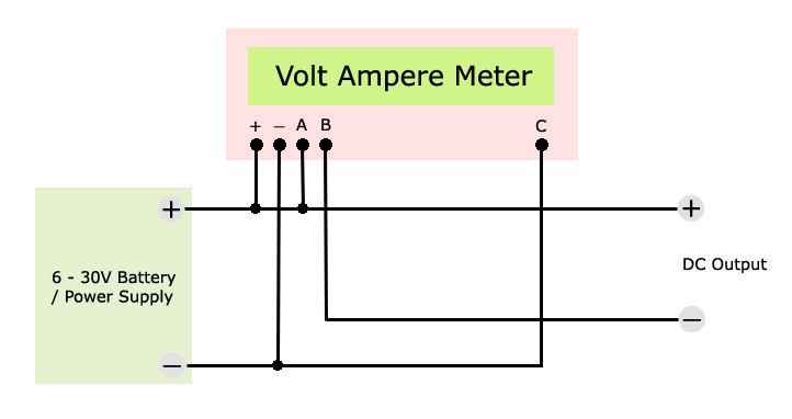
How to wire digital dual display volt- and ammeter - DIY Projects
PDF Voltmeter — Instructions Voltimetro - Instrucciones ... WIRE NUT FLAT WASHER NUT WASHER VOLTMETER GROMMET U-BRACKET DO NOT LEAVE ANY HARDWARE OUT OF THESE CONNECTIONS Diagram 1 ground source (Step 2) should be connected as shown in Diagram 1, to the voltmeter's connection post marked "-". 5. The wire from the fuse box (Step 3) should be connected as shown in Diagram 1, to the voltmeter's ...
Amp to Volt meter question | Chevy Tri Five Forum
(PDF) Basic Electrical House Wiring | abdulaziz hassan ... The voltmeter is shown in a circuit diagram as a V in a circle, and it acts as another resistor. To prevent the voltmeter from changing the current in the circuit (and therefore the voltage across the resistor), The voltmeter must have a resistance much larger than that of the resistor. If the resistance of the voltmeter is large, only a negligible current flows through the meter. Puntland ...
0.28 Inch LED Mini DC Voltmeter
GENERATOR WIRING DIAGRAM - Multiquip Inc voltmeter frequency meter circuit breaker, 3p 1600a panel light selector switch il1, il2 v ~ symbol designation a~ ac.ammeter as change-over switch, ammeter. dca1100ssc 60 hz generator • operation manual — rev. #0 (07/20/17) — page 47 generator wiring diagram (main breaker) 125: 125 mm2 100: 100 mm2 80: 80 mm2 22: 22 mm2 14: 14 mm2 mm2 code/ wire color b l br …
MAD Wiring with Autometer Voltmeter already installed | For A ...
Autometer Gauge Wiring Diagram - Wiring Diagram Autometer Voltmeter Wiring Diagram Perfect Modern Voltmeter Gauge - Autometer Gauge Wiring Diagram. Wiring Diagram not just offers detailed illustrations of everything you can perform, but in addition the processes you ought to stick to whilst carrying out so. Not merely can you locate various diagrams, however you also can get step-by-step ...

DROK 0.28 Inches LED Ultra-Small DC Digital 0-100V Voltmeter ...
Voltmeter Wiring - Hot Rod Forum The wiring will need to be series and not parallel as a volt meter is wired, in the diagram posted earlier. The AMP gauge sits in the middle of the electrical system, monitors all loads, lights, starter .. whatever when activated. Light 15 amps starter 30 amps, and so one.
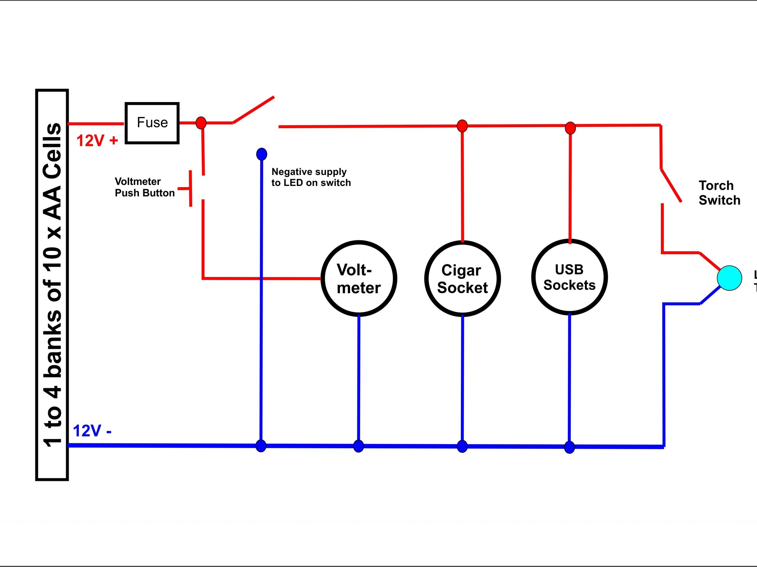
How to make a portable power supply - Practical Motorhome
Voltmeter Gauge Wiring Diagram - autocardesign Voltmeter Gauge Wiring Diagram - wiring diagram is a simplified customary pictorial representation of an electrical circuit. It shows the components of the circuit as simplified shapes, and the facility and signal contacts with the devices. A wiring diagram usually gives counsel roughly the relative tilt and concurrence of devices and ...

Voltmeter Wiring Diagram Tools Stock Photo (Edit Now) 608567852
Sunpro Voltmeter Wiring Diagram DIAGRAM 1. In the automotive context, a voltmeter gauge displays the number of volts stored by the vehicle's battery. Sunpro manufactures volt gauges that instead feature a. Attach one end of the wire to a clean ground source, such as a metal panel. tion posts of the voltmeter Diagram 1. 2.
Wiring Diagram Voltage Regulator Voltmeter Gauge, PNG ...
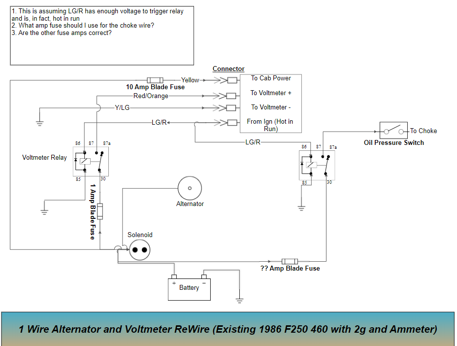
1 Wire Alternator and Voltmeter Rewire Diagram - Ford Truck ...

Black Voltmeter and a Wiring Paper Diagram Stock Image ...

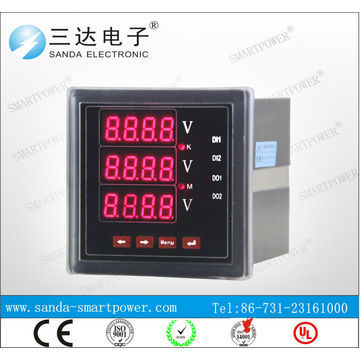
VOLTMETER WIRING DIAGRAM. 3 PHASE DIGITAL VOLTMETER WIRING DIAGRAM
Wiring guide for anyone wanting to put a 2 wire voltmeter ...
Switch and dual voltmeter wiring help | Tacoma World
Volt meter - The Hull Truth - Boating and Fishing Forum
Voltmeter Wiring | Hot Rod Forum

Wiring diagram of DC Voltmeter | Download Scientific Diagram

My Plan for Stryfe wiring for door activated voltmeter and ...
Rs485 Modbus 220v Termianl Wiring Diagram Digital Ammeter and ...
How to Wire Voltmeter Gauges on a Car
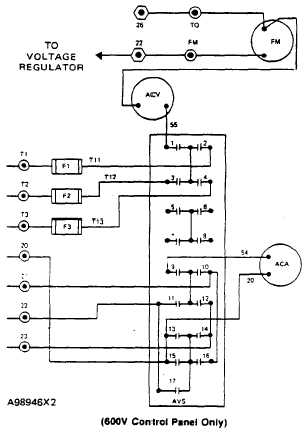
AMMETER/VOLTMETER SELECTOR SWITCH (AVS) WIRING DIAGRAMS - TM ...

Install Guides - Solid Kit

Gauge Voltmeter Wiring diagram, Voltmeter, electronics ...

VDO ViewLine Voltmeter 18-32V Black 52 mm

MG Midgets: Amps vs. Volts?

AC And DC Voltmeter Wiring Diagram

Voltmeter Gauge with Digital Display | Wema UK

DIGIFIZmini - Voltmeter
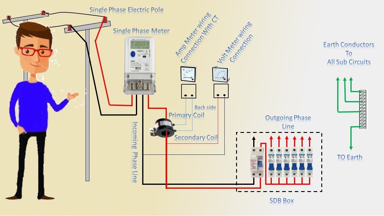
How to ammeter & voltmeter connection Single phase | Ampmeter | Voltmeter | Earthbondhon
![Article [13] - ST1300 - Voltmeter Install | ST1300 Articles ...](http://s9.postimg.cc/bhg5tpynz/Conexiones_Rel.jpg)
Article [13] - ST1300 - Voltmeter Install | ST1300 Articles ...

voltage measurement - What is the white wire for on this ...
2" Voltmeter


Comments
Post a Comment