42 control 4 wiring diagram
wiring diagrams - Field Controls Wiring Diagram for models CAS-4, CAS-4Jr., 6, 7, and PVG Chimney Vent, Two 24 volt Gas Appliances with CAC-24 Combustion Air Controller. English. CAS-3, 6, and 7 with Riello Burner Wiring Diagram. Wiring Diagram fro models CAS-3, 6, and 7 with Riello Burner with or without stack damper. Wiring Guide for Smart Home Building | Home Automation Blog Wiring Guide for Smart Home Building. February 22, 2014. It's starting to feel a little spring-like in Utah, and unlike much of the country where major snow and ice storms in December and January have stunted winter home-building efforts, we're starting to see a lot of new construction. The big building season is starting to heat up, much ...
PDF for existing homes & new construction - Control4 other seamlessly. If done correctly, proper wiring can save money, time and frustration. The type of wiring required for a home automation system is called structured wiring. Structured wiring is a general term that refers to a whole-house network of audio, video, data, telephone, home automation components or security signals.
Control 4 wiring diagram
PDF Control4® Panelized Lighting: Reference Guide for Electricians Figure 1). Panelized lighting utilizes a centralized/star wiring configuration, where circuits from the breaker box are routed first to a centrally-located enclosure (panel), which houses dimmer, relay, and other system control modules. From there, the switched/dimmed circuits are routed directly to the loads (see Figure 2). 8-Channel Dimmer Wiring Guide - Control4 Wiring Guide Diagrams Color Code: Black Line Red Load Grey Neutral Green Earth Ground Blue Ethernet Figure 1. Wiring in Control4 Panel Wiring Diagrams Use the Control4® 8-Channel Dimmer wiring diagrams along with the 8-Channel Dimmer Installation Guide to install 8-Channel Dimmers. ™ Essential Lighting Wiring Guide - Control4 This diagram shows a sample 4-way wiring configuration using an Essential Forward Phase Dimmer (C4-V-FPD120) or Switch (C4-V- SW120-277) with two Essential Auxiliary Keypads (C4-V-AUX). Daisy-chain each additional Auxiliary Keypad by extending the Ground, Traveler, and Neutral to each keypad. 4-way configuration
Control 4 wiring diagram. Control4 Thermostat Wiring Diagram - schematron.org Sep 27, 2018 · Control4 Thermostat Wiring Diagram. Control4 Wireless Thermostat Installation Guide and the Control4. Wireless Thermostat User Guide. IMPORTANT! Using this product in a manner other than . This Control4® Wireless Thermostat enables intelligent HVAC control as part of a Changing this setting is described in Step 14, “Installation Instructions. PDF Basic Wiring for Motor Contol - Eaton control circuit may not be at the same voltage as the power circuit. When the voltage of the control and power circuits is the same, it is referred to as Common Control. If the volt-ages are different, it is called Separate Control. Figure 4. Typical Starter Wiring Diagram — Three-Phase Separate voltages supplied by different voltage sources. Standard Control4 Wiring Diagrams - Driver Discussion ... Standard Control4 Wiring Diagrams Standard Control4 Wiring Diagrams. By andy.cytexone, January 6, 2006 in Driver ... the designing phase of a new home and was thinking about incorporating C4 in my house while the house is all studs and wiring is being pulled. Link to comment Share on other sites. More sharing options... Gene. Posted ... Access Control Cables and Wiring Diagram | Kisi Magnetic Lock Wiring Diagram Much like the door access control system diagram above, the mag lock wiring diagram relies on a few simple basics: electricity supply, switches, and, of course, locks. Magnetic locks , also referred to as mag locks or maglocks for short, rely on a constant flow of electricity to stay sealed.
Control 4 Wiring Diagram - Free Wiring Diagram Variety of control 4 wiring diagram. A wiring diagram is a simplified traditional photographic representation of an electric circuit. It shows the components of the circuit as streamlined shapes, and the power as well as signal links between the gadgets. Trailer Wiring Diagram 4 Wire - Wiring Sample This guide will be discussing 4 wire trailer wiring diagram troubleshooting. The four wires control the turn signals brake lights and taillights or running lights. 4 way trailer connectors are. Start by cutting the white wire and attaching it to the trailer frame. Can trailer 4 way be ran to trailer with 8 wires for trailer wiring. PDF Configurable Wired Keypad Installation Guide ctrl4.co/buswiring Wiring diagrams For bus wiring details, refer to the Keypad Bus Wiring Guide(ctrl4.co/buswiring). Operation and configuration On initial power up, all status LEDs on the keypad will illuminate green, indicating that the device has power. Until the keypad has been configured into a Control4 system, it will not control any loads. Control4 Ldz-101 Wiring Diagram 3 Way Switch Control4 Ldz-101 Wiring Diagram 3 Way Switch 19.10.2018 4 Comments So, the control4 diagram example is different. Line in downstairs (where and three way switches. C4 really just simulates a three way switch. LSZX Wireless Switch Exhibit 8 details for FCC ID R33LSZ made by at Wall Box To wire the switch for a Control4 3-way-switch environment when.
artofcomm.de treadmill control board circuit diagram. 20s Treadmill electronic console. repair treadmill circuit and troubleshooting procedure without service manualVariable Frequency Drive (V Fabulous Control4 Wiring Schematic Sew Motor Diagram Assortment of control 4 wiring diagram. A wiring diagram is a simplified traditional photographic representation of an electric circuit. The following tips apply to either a new home or an existing home. Control4 Essential Lighting Wiring Diagrams Essential Forward Phase Dimmer, 120V (White) Installation Guide. Essential Lighting Professional Wiring Guide. Essential Lighting Comparison. Essential Switch, 120V/277V (White) Data Sheet. Essential Switch, 120V/277V (White) Installation Guide. Plug-In Outlet Dimmer Data Sheet. Plug-In Outlet Dimmer Installation Guide. Control4 Home Automation Wiring Diagram - U Wiring Jul 25, 2021 · Control4 home automation wiring diagram. A wiring diagram is a streamlined standard pictorial representation of an electrical circuit. It installs in a standard back box using typical wiring standards and communicates to the Control4 system using a wireless connection. Control 4 Wiring Diagram General Wiring Diagram.
8-Channel Dimmer Wiring Guide
Control Panel Wiring Diagrams - Wiring Diagram and ... Self Adhesive Wiring Diagram For Control Panel Rangvishwa Enterprises Id 10541553097. Basic Electrical Design Of A Plc Panel Wiring Diagrams Eep. Bernini Design 160kva Ats Control Panel Wiring Diagram The Be28 Panels Are Manufactured In Range 15 Up To Basic Configuration Features An Alarm Output Relay And Two Configurable.

Smart Home Wiring Guides
Control 4 Switch Wiring Diagram - Wiring Diagram And ... Wiring Diagram For 4-way switch: More than three locations to control light fixtures utilizes 3-way switches at the end of the switched circuit and 4-way switches in the middle.

Installation of a Control4 Panelized Lighting System
PDF Wiring Diagram Book - Daltco Typical Controller Markings Typical Elementary Diagram IEC Typical Controller Markings Typical Elementary Diagram Table 4 Control and Power Connections for Across-the-Line Starters, 600 V or less (From NEMA standard ICS 2-321A.60) 1-Phase 2-Phase, 4-Wire 3-Phase Line Markings L1, L2 L1, L3: Phase 1 L2, L4: Phase 2 L1, L2, L3 Ground, when used
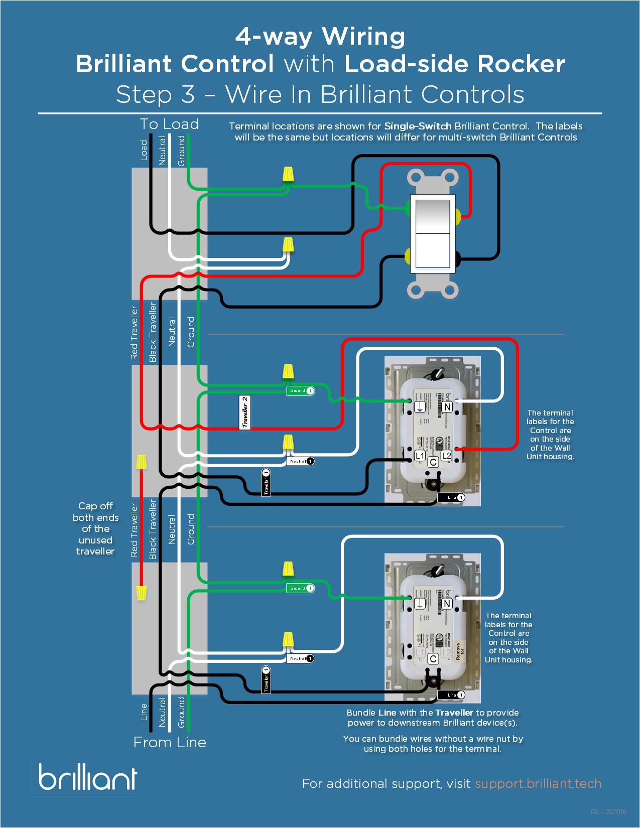
Brilliant Control 4-way Wiring Guide – Brilliant Support
PDF SAMPLE WIRING DIAGRAMS - SDC Security all wiring must conform to national, state, and local codes for class 2fire protection and control devices 3. always consult with the authority having jurisdiction (ahj) beforeinstallation. 4. where required by code, connect failsafe systems to the local fire life safetysystem for emergency release. 5.
Wiring Guide for Smart Home Building | Home Automation Blog
Essential Lighting Wiring Guide - Control4 This diagram shows a sample 4-way wiring configuration using an Essential Forward Phase Dimmer (C4-V-FPD120) or Switch (C4-V- SW120-277) with two Essential Auxiliary Keypads (C4-V-AUX). Daisy-chain each additional Auxiliary Keypad by extending the Ground, Traveler, and Neutral to each keypad. 4-way configuration
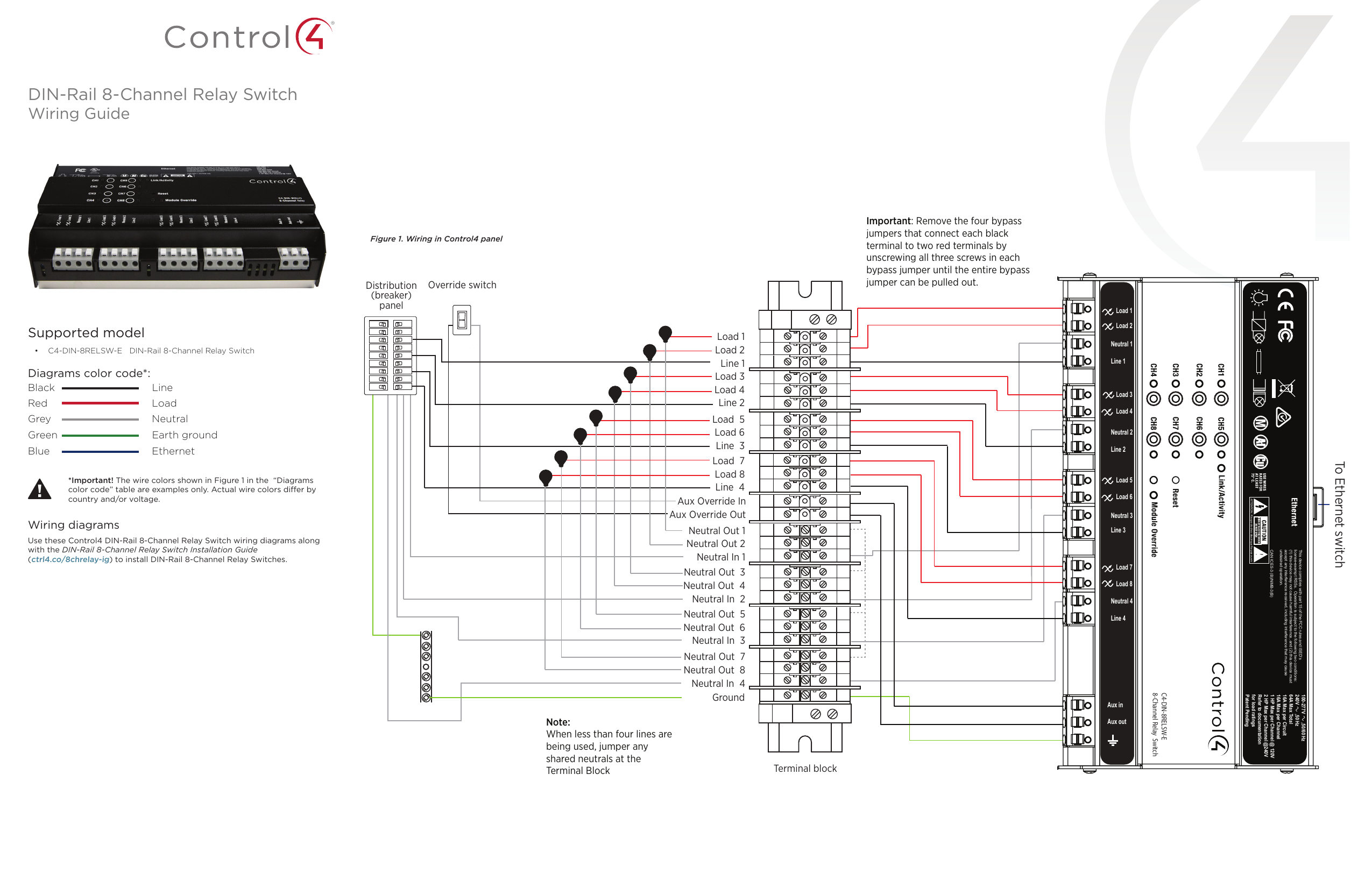
Control4 C4-DIN-8REL-E 8-Channel Relay Guide | Manualzz
8-Channel Dimmer Wiring Guide - Control4 Wiring Guide Diagrams Color Code: Black Line Red Load Grey Neutral Green Earth Ground Blue Ethernet Figure 1. Wiring in Control4 Panel Wiring Diagrams Use the Control4® 8-Channel Dimmer wiring diagrams along with the 8-Channel Dimmer Installation Guide to install 8-Channel Dimmers. ™

Building New Home and Committed to Distributed A/V - Please ...
PDF Control4® Panelized Lighting: Reference Guide for Electricians Figure 1). Panelized lighting utilizes a centralized/star wiring configuration, where circuits from the breaker box are routed first to a centrally-located enclosure (panel), which houses dimmer, relay, and other system control modules. From there, the switched/dimmed circuits are routed directly to the loads (see Figure 2).
C4DIM1Z Wireless Dimmer User Manual 200 ...

Three way wiring - Question & Answer - c4forums | The ...
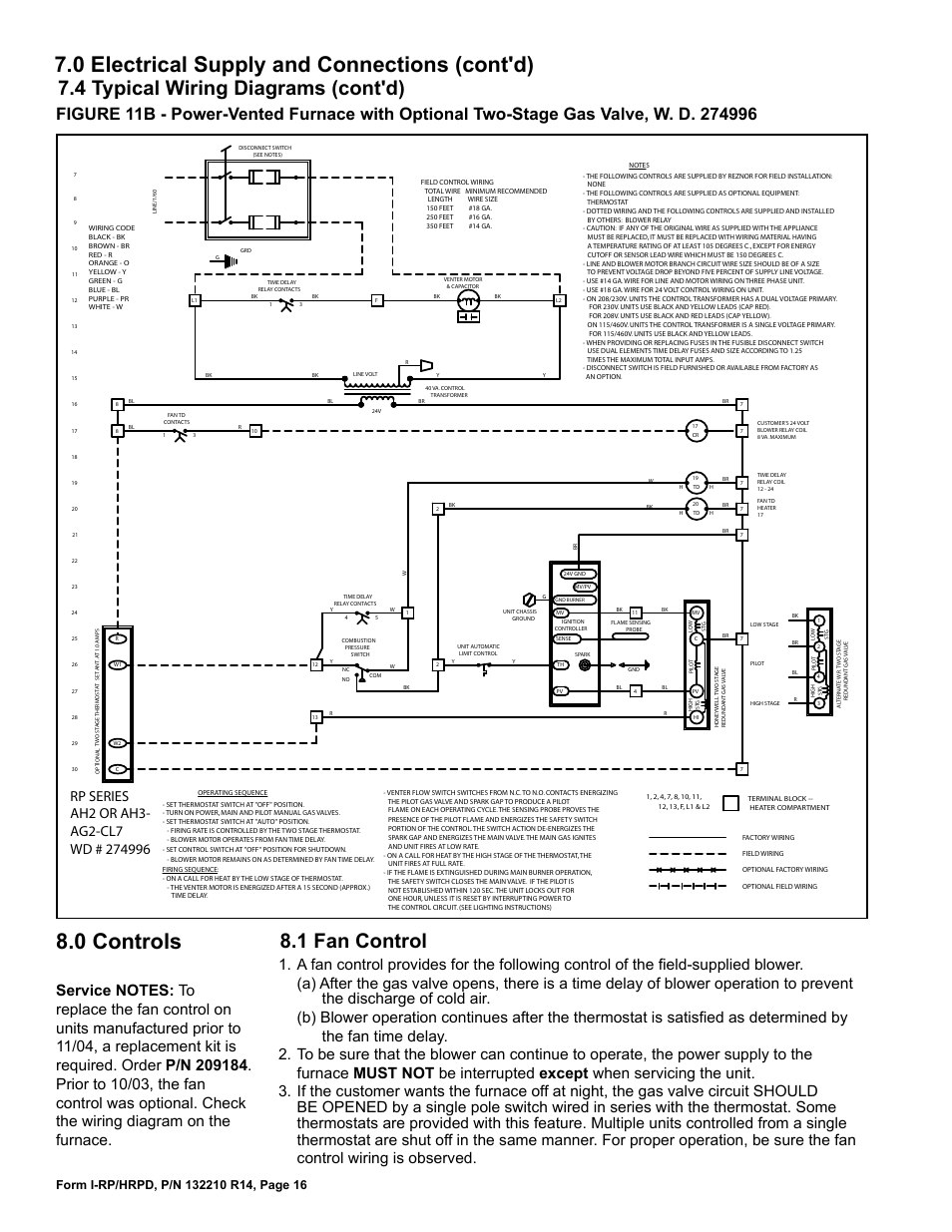
1 fan control, 4 typical wiring diagrams (cont'd) | Reznor ...
Rf 2.4g Panel Control 4 Kanal Led Dimmer Controller Für ...
200-00061 Rev A_WirelessDimmer.fm

Control4 Dimmer Lighting Wireless light switch Wiring diagram ...

Control4 8-Kanal 0-10V Dimmer Benutzerhandbuch - Handbücher+

C4FPD DIMMER WITH ZIGBEE User Manual Control4
SRP-2305-10L-CC-MULTIDIM 10W DALI DIMMABLE LED DRIVER

This Video Covers the Control4 Panelized Lighting System

How to wire a control4 3-way switch

Loco Wiring: Hand Control & Horn Relay Board - 4QD - Electric ...

Control4 LDZ1011 LDZ-101-X Controllable Dimmer User Manual ...
Wireless Puck Dimmer and Switch Module Installation Guide

TerminalBlockWiringGuide_Online | Manualzz

Control4 Panelized Lighting - Wiring

8-Channel Relay Wiring Guide - Control4 · PDF ...
8-Channel 0-10V Dimmer Wiring Guide

Wiring diagram of the controller system. | Download ...
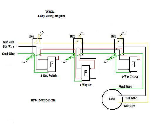
Wiring a 4-way switch

Control4 Terminal Blocks Guide | Manualzz
Wiring diagram of the pump controller. | Download Scientific ...
8-Channel 0-10V Dimmer Wiring Guide
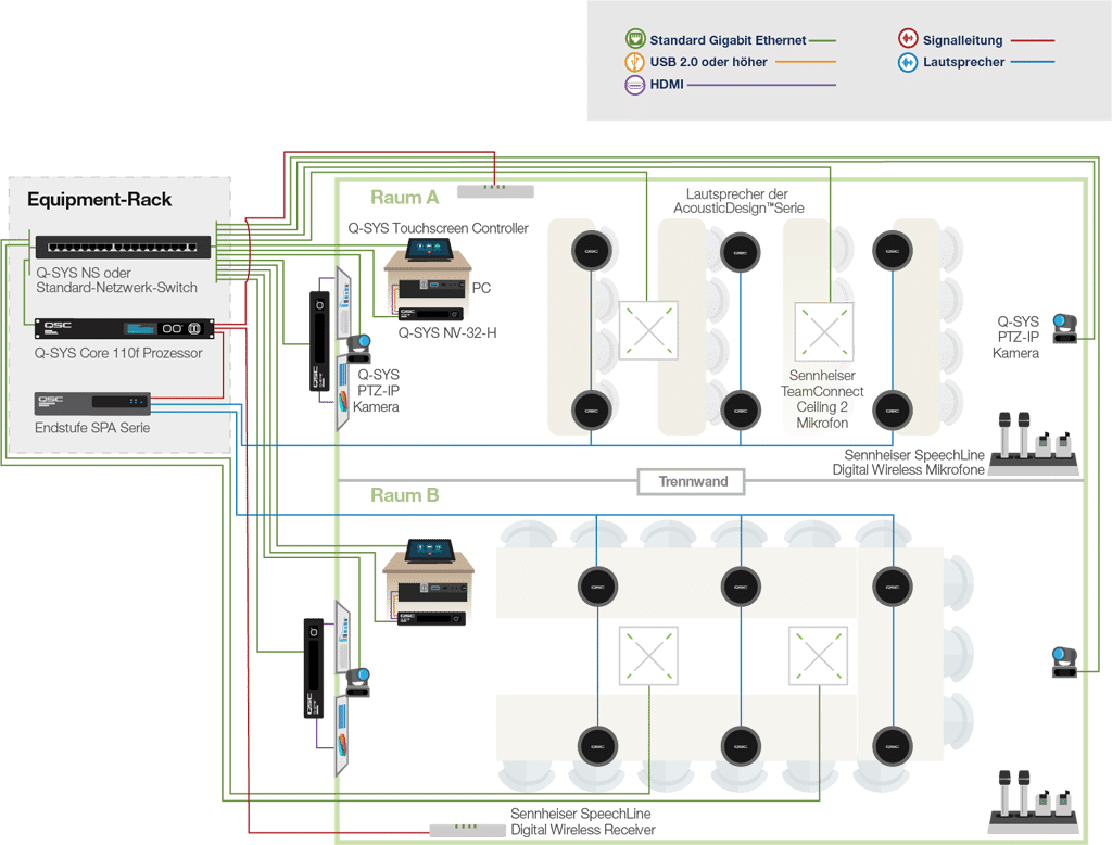
QSC mit dediziertem, für Microsoft Teams zertifiziertem ...
8-Channel 0-10V Dimmer Wiring Guide
Control4/RS-232 Serial Pinout .3Mb

7 Control4 ideas | home automation, control4, smart home
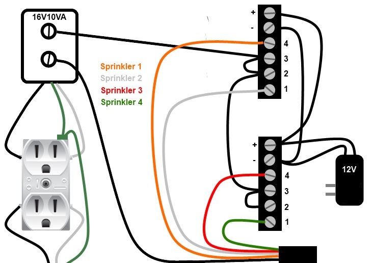
DIY Control4 sprinkler control | Garp

Someone tell me how to integrate this? - General Control4 ...

Help Wiring Door Strike to DS2 - Question & Answer - c4forums ...
C4FS1Z Wireless Fireplace Switch User Manual 200 ...
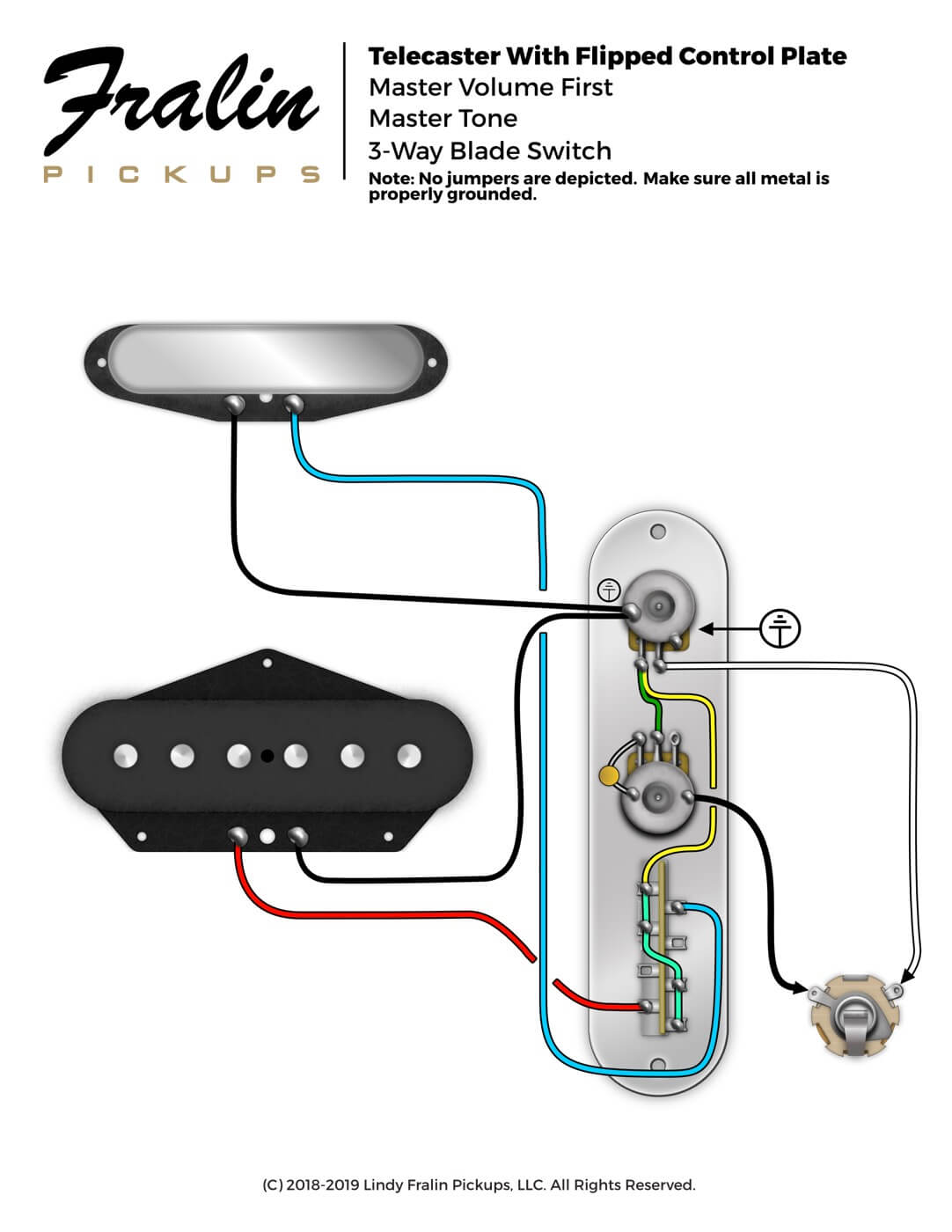
Telecaster Wiring Diagram - Flipped Control Plate - Fralin ...

Smart Home Wiring Guides
Reverse control plate with a 4-way switch? | Telecaster ...

Control 4 Switch Wiring Diagram - Wiring Diagram And ...


Comments
Post a Comment