41 vapor compression cycle diagram
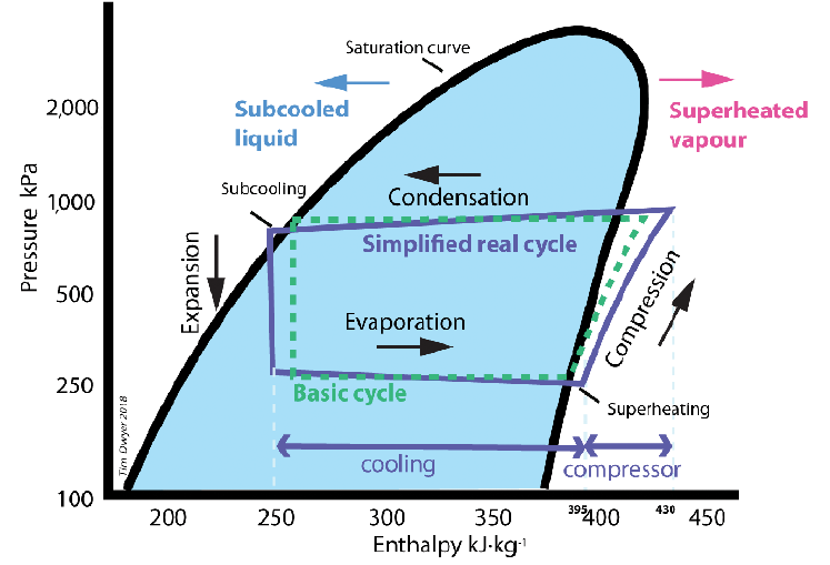
cdn.ymaws.com › www › resourceHow does basic refrigeration cycle work? Understanding the basic refrigeration cycle diagram also helps us to find subcooled, superheat and to troubleshoot refrigeration processes much easier. Finding subcooled and superheat is beyond the scope of this discussion. As you can see in the Ph diagram below. Saturation curve this curve represents what state (vapor or liquid) and Refrigeration Cycle - Components, Diagram, Stages ... Refrigeration Cycle Diagram Vapor Compression Cycle. Vapour Compression Refrigeration Cycle is the most widely used refrigeration system. Vapor-compression cycle refrigeration is a process that uses the physics of phase change heat transfer and the unique properties of a refrigerant to transfer heat from a relatively cold source to a hot medium.
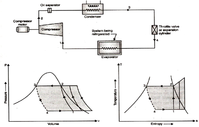
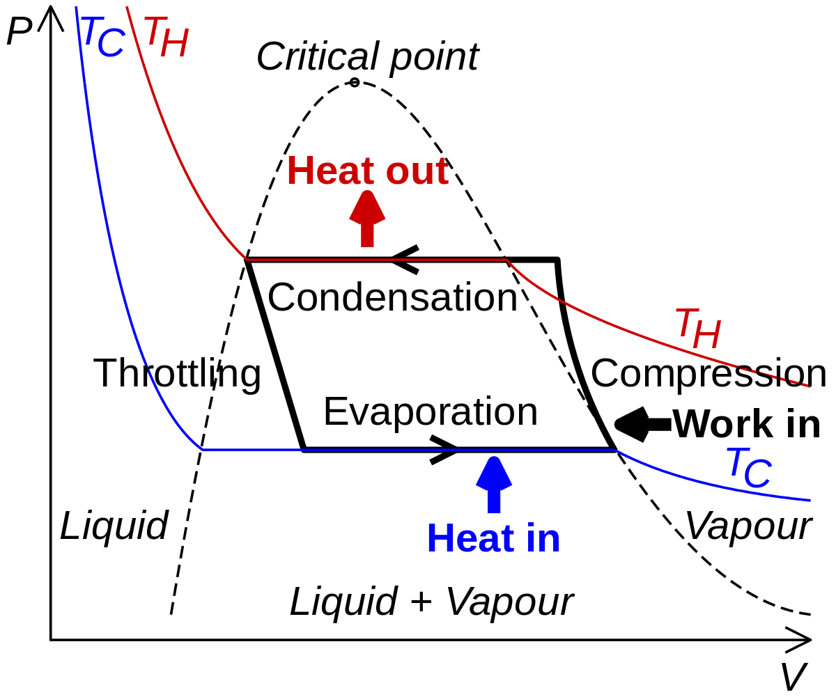
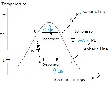
Simple Vapour Compression Refrigeration System (with ... Simple Vapour Compression Cycle on P-h Chart: A simple vapour compression cycle is shown by 1—2—3—4—1 on P-h chart of Fig. 36.24. 1- 2 Isentropic compression in compressor. 2- 3 Constant pressure cooling (Heat rejection). 3- 4 Isenthalpic expansion through expansion valve. 4- 1 Constant pressure heat absorption.

Vapor compression cycle diagram
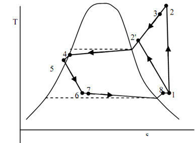
PDF Vapor Compression Refrigeration Cycle Figure 5- Schematics of a vapor compression refrigeration cycle. For thermal analysis of refrigeration cycle several diagrams such as 6 F O or L F D diagrams can be used. The pressure diagram of an ideal refrigeration cycle shown in Fig. 6, includes the following processes: sites.ntc.doe.gov › partners › trTHERMODYNAMICS, HEAT TRANSFER, AND FLUID FLOW Module ... - Energy Department of Energy Fundamentals Handbook THERMODYNAMICS, HEAT TRANSFER, AND FLUID FLOW Module 1 Thermodynamics Comparison of Actual and Theoretical Vapor Compression Cycle Actual vapor compression cycle is different from theoretical vapor compression cycle. In actual vapor compression cycle condensation and evaporation do not occur at constant pressure. ... In the diagram it is indicated by the process represented by line 6-7. The major difference between ideal and actual vapor compression cycle in throttling is ...
Vapor compression cycle diagram. PDF Refrigeration Cycle - Simon Fraser University Actual Vapor‐Compression Refrigeration Cycle Fig. 5-4: T-s diagram for actual vapor-compression cycle. Most of the differences between the ideal and the actual cycles are because of the irreversibilities in various components which are: 1-In practice, the refrigerant enters the compressor at state 1, slightly superheated vapor, instead of ... Compression Cycle - an overview | ScienceDirect Topics Temperature-entropy diagram for ideal vapour compression cycle. Expansion is a constant enthalpy process, shown as a vertical line on the P-h diagram. No heat is absorbed or rejected during this expansion, the liquid just passes through a valve. Design of Vapor-Compression Refrigeration Cycles The design is to be based upon the ideal vapor-compression refrigeration cycle, with four components: a cooler (where we reject the heat), a throttle, a heater (where we absorb the heat), and a compressor. ... The T-s diagram for a vapor-compression refrigeration cycle is shown below. Figure 1: Vapor-Compression Refrigeration Cycle › engineering › carnot-cycleCarnot Cycle - an overview | ScienceDirect Topics Nevertheless, the alternative Carnot vapor cycle comes with other problems such as isothermal heat transfer at variable pressures and isentropic compression to extremely high pressures. Therefore, it is stated that the Carnot vapor cycle cannot be approximated in actual vapor driven systems [6].
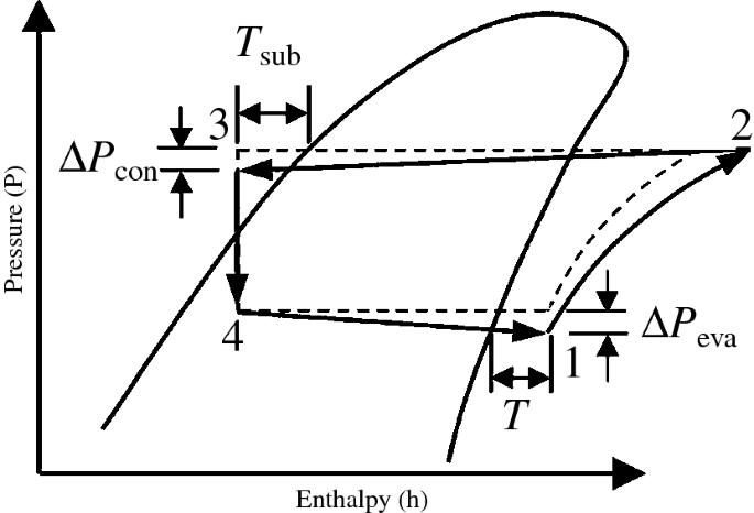
The p-h diagram and the vapor-compression cycle (Journal ... This paper reports that the representation of the p-h diagram for the thermodynamic vapor-compression cycle found in educational textbooks is misleading, and a suggestion for future presentation is made. Authors: Klausner, J F; Mei, R [1] + Show Author Affiliations. Florida Univ., Gainesville, FL (United States). Dept. of Mechanical Engineering. What is Vapor-compression Cycle - Refrigeration Cycle ... Vapor-compression cycle - Thermodynamic cycle of heat pumps. The vapor-compression uses a circulating liquid refrigerant as the medium (usually R134a) which absorbs and removes heat from the space to be cooled and subsequently rejects that heat elsewhere. The figure depicts a typical, single-stage vapor-compression system. PDF CHAPTER FOUR 4. Typical Vapour-Compression System 4.5. Actual vapour compression cycle Fig. 19. T-S diagram for actual Vapour Compression cycle. The actual vapour compression cycle is different from the theoretical vapour compression cycle in many ways. The main deviations between the theoretical and actual cycle are: (1) Vapour refrigerant leaving the evaporator is in superheated state. Mechanism And Working Of A Vapour Compression ... The above fig gives the general idea of the refrigeration cycle. Note that there are different vapour compression cycles. Which are listed below 1. Cycle with dry saturated vapour after compression 2. Cycle with wet vapour after compression 3. Cycle with superheated vapour after compression 4. Cycle with superheated vapour before compression 5. Cycle with sub-cooling of refrigerant Read : COP ...
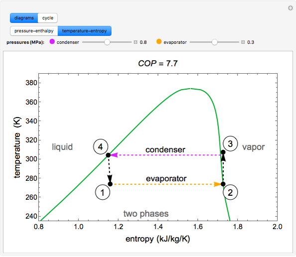
P-h diagram of vapor compression refrigeration cycle ... The vapor compression refrigeration cycle consists of four processes: (1-2) compressing refrigerant in compressor isentropically, (2-3) condensation at constant pressure, (3-4) adiabatic expansion... Ordinary Vapor Compression (OVC) Cycle for Refrigerant R ... Pressure-enthalpy and temperature-entropy diagrams for refrigerant R-134a are used to demonstrate an ordinary vapor compression (OVC) cycle.You can vary the condenser pressure (high pressure) and the evaporator pressure (low pressure) with sliders. The coefficient of performance (), which is the heat transferred to the evaporator divided by the compressor work , is calculated. Vapour Compression Refrigeration Cycle: Components ... Vapour Compression Refrigeration Cycle is the most widely used refrigeration system. In this system, the working fluid is a vapor. It readily evaporates and condenses or changes alternatively between the vapor and liquid phase without leaving the refrigerating plant. During evaporation, it absorbs heat from the cold body and this heat is used ... Vapor Compression - an overview | ScienceDirect Topics Schematic diagram of TVC distillation. From H. El-Dessouky, H. Ettouney, Single-effect thermal vapor-compression desalination process: thermal analysis, Heat Transfer Eng. 20 (1999) 2. ... Figure 8.3 shows how the vapor compression cycle compresses, condenses, expands, and boils refrigerant to provide cooling. The bullet points below describe ...
STANDARD VAPOUR COMPRESSION CYCLE
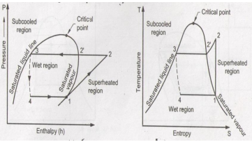
Vapour compression cycle - working, diagrams, uses, COP ... P-H and T-S Diagrams of vapour compression cycle Explanation: The dry saturated vapour enters the compressor, this is shown as point 1 in the chart above. This compressor increases the pressure of the dry saturated vapour from the evaporator pressure to condenser pressure. During the compression, the dry saturated vapour's temperature increases.
Vapour Compression Refrigeration Cycle: - Engineering Tutorials
› files › eContentVAPOR COMPRESSION REFRIGERATION SYSTEM (VCRS) Introduction Simple Vapor Compression Refrigeration system, Analysis of vapor compression cycle, Use of T-s and P- h charts, Effect of change in suction and discharge pressures on C.O.P Effect of sub cooling of condensate & superheating of refrigerant vapor on C.O.P of the cycle, Actual vapor compression refrigeration cycle
Explain vapour compression refrigeration cycle on T-S and p-h ...
What is Refrigeration Cycle? Basic, Diagram & Explanation ... Refrigerant Cycle Description & Diagram. All refrigerating equipment & air conditioners work based on refrigeration cycles. We are discussing mainly the vapor compression cycle in this article. In another refrigeration cycle, namely vapor absorption is used in case of waste heat is available. It will be discussed in another article.

New refrigerants and system configurations for vapor ...
PDF UNIT 2 REFRIGERATION CYCLE Refrigeration Cycle Vapour after Compression A vapour compression cycle with dry saturated vapour after compression is shown on T-s diagrams in Figures 2.2(a) and (b) respectively. At point 1, let T 1, p 1 and s 1 be the temperature, pressure and entropy of the vapour refrigerant respectively. The four processes of the cycle are as follows : (a) T-s Diagram (b) p ...
Vapor-compression refrigeration - Wikipedia
PDF Case 1: The Basics of Refrigeration Cycle P.H. Diagram ... single stage compression refrigeration systems which are based on the same CT, ET and ... Figure 1-2 Properties of Liquid and Saturated Vapor for R-22, -50℉ to 14℉. Figure 1-3 Saturated Properties for R-22, 10℉ to 64℉ . ... Figure 1-5 Refrigeration Cycle on the P-H Diagram Take the structure image of this refrigeration cycle from Figure ...
Actual Vapor Compression Cycle, Standard Rating Cycle ...
Ph diagram for a vapour compression cycle | Physics Forums The Attempt at a Solution. I am trying to understand the above ph diagram (for a vapour compression cycle), In some examples, point 1 is situated as above in the image (i.e. to the right of the saturated vapour line) and at other times it's situated exactly where I drew the purple arrow (i.e. on the saturated vapour line).

Vapour Compression Cycle | Definite Guide (With Video & Diagram)
P-H Diagram Thermodynamics | HVAC and Refrigeration PE ... In order to properly understand this diagram, it is best to go through the vapor compression cycle on a P-H diagram. Understanding the P-H Diagram. On the P-H diagram, pressure is indicated on the y-axis and enthalpy is indicated on the x-axis. Typically enthalpy is in units of Btu/lb and pressure is in units of pounds per square inch (psi).

T-s diagram of the vapour-compression refrigeration cycle ...
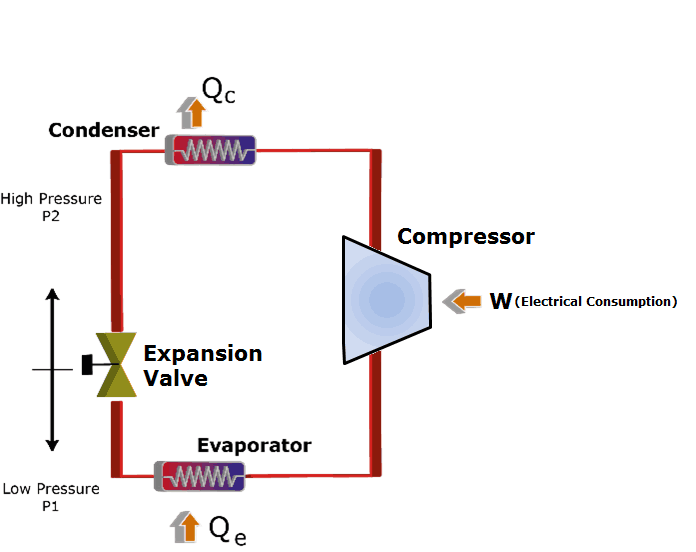
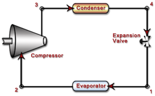
Vapor Compression System | Compression Cycle | ARANER The Vapor Compression Refrigeration Cycle involves four components: compressor, condenser, expansion valve/throttle valve and evaporator. It is a compression process, whose aim is to raise the refrigerant pressure, as it flows from an evaporator.

Ch10, Lesson B, Page 2 - The Ideal Vapor-Compression ...
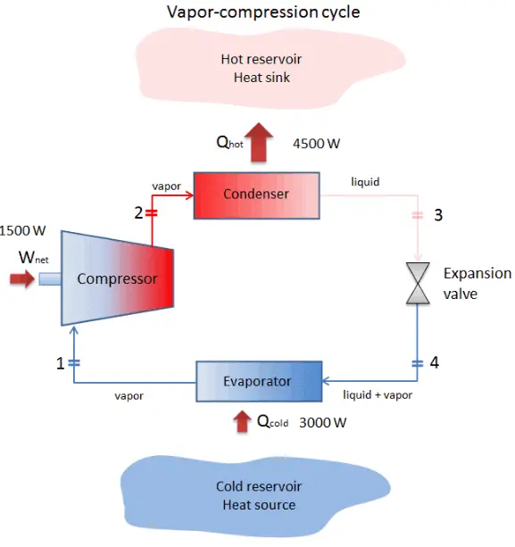
Vapor Compression Refrigeration System | Basic, Working ... Vapor Compression Cycle -Working Diagram. A refrigeration system can also be used as a heat pump, in which the useful output is the high-temperature heat rejected at the condenser. Alternatively, a refrigeration system can be used for providing cooling in summer and heating in winter. Such systems have been built and are available now

B) Draw T-S, P-H diagrams of vapour compression refrigeration ...
Explain vapour compression refrigeration cycle on T-S and ... the p-h and t-s diagram for the simple vapor compression refrigeration cycle is shown in the figure for vapour entering the compressor is in dry saturation condition the dry and saturated vapour entering the compressor at point 1 that vapour compresses isentropic ally from point 1 to 2 which increases the pressure from evaporator pressure to …

Vapor-compression refrigeration - Wikipedia
Vapour Compression Cycle | Definite Guide (With Video ... P-V, T-S, P-H DIAGRAM OF VCC Actual Vapour Compression Cycle The actual vapour compression cycle differs from the standard cycle due to the following reasons: liquid refrigerant in the condenser is subcooled to ensure 100% liquid entering the expansion valve.

Vapor-compression refrigeration - Wikipedia
Answered: A vapor-compression refrigeration… | bartleby A vapor-compression refrigeration system operates on the cycle shown below. The refrigerant is tetrafluoroethane. For the following set of operating conditions, determine the circulation rate of the refrigerant, the heat-transfer rate in the condenser, the power requirement, the coefficient of performance of the cycle, and the coefficient of performance of a Carnot refrigeration cycle ...

Theoretical Vapour Compression Cycle (Automobile)
Vapor-compression refrigeration - Wikipedia Figure 2: Temperature-Entropy diagram The thermodynamics of the vapor compression cycle can be analyzed on a temperature versus entropy diagram as depicted in Figure 2. At point 1 in the diagram, the circulating refrigerant enters the compressor as a saturated vapor.

How does a Refrigeration Cycle work? | What is Refrigeration?
PDF Chapter 10: Refrigeration Cycles - Saylor Academy The ideal vapor-compression cycle consists of four processes. Ideal Vapor-Compression Refrigeration Cycle Process Description ... 4-1 Constant pressure heat addition in the evaporator . Chapter 10-5 The P-h diagram is another convenient diagram often used to illustrate the refrigeration cycle. The ordinary household refrigerator is a good ...

Schematic diagram of a typical vapor compression ...
Comparison of Actual and Theoretical Vapor Compression Cycle Actual vapor compression cycle is different from theoretical vapor compression cycle. In actual vapor compression cycle condensation and evaporation do not occur at constant pressure. ... In the diagram it is indicated by the process represented by line 6-7. The major difference between ideal and actual vapor compression cycle in throttling is ...

Vapor Compression Refrigeration Systems - Refrigerator ...
sites.ntc.doe.gov › partners › trTHERMODYNAMICS, HEAT TRANSFER, AND FLUID FLOW Module ... - Energy Department of Energy Fundamentals Handbook THERMODYNAMICS, HEAT TRANSFER, AND FLUID FLOW Module 1 Thermodynamics
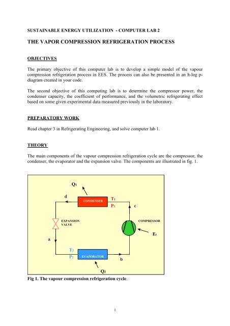
THE VAPOR COMPRESSION REFRIGERATION PROCESS - KTH
PDF Vapor Compression Refrigeration Cycle Figure 5- Schematics of a vapor compression refrigeration cycle. For thermal analysis of refrigeration cycle several diagrams such as 6 F O or L F D diagrams can be used. The pressure diagram of an ideal refrigeration cycle shown in Fig. 6, includes the following processes:

Vapor Compression Refrigeration System | Basic, Working ...

Refrigeration; Vapor Dome; Hand-pump Refrigerator ...

Compression Refrigeration Systems | Turbomachinery blog

A vapor compression refrigeration system circulates ...
ordinary-vapor-compression-cycle-refrigerant-r-134a - LearnChemE

Vapor-Compression Refrigeration Cycle (Interactive Simulation)
Could somebody please explain the vapor compression cycle ...

Vapour Compression Refrigeration System Theteche.com
What is Vapor-compression Cycle - Refrigeration Cycle ...
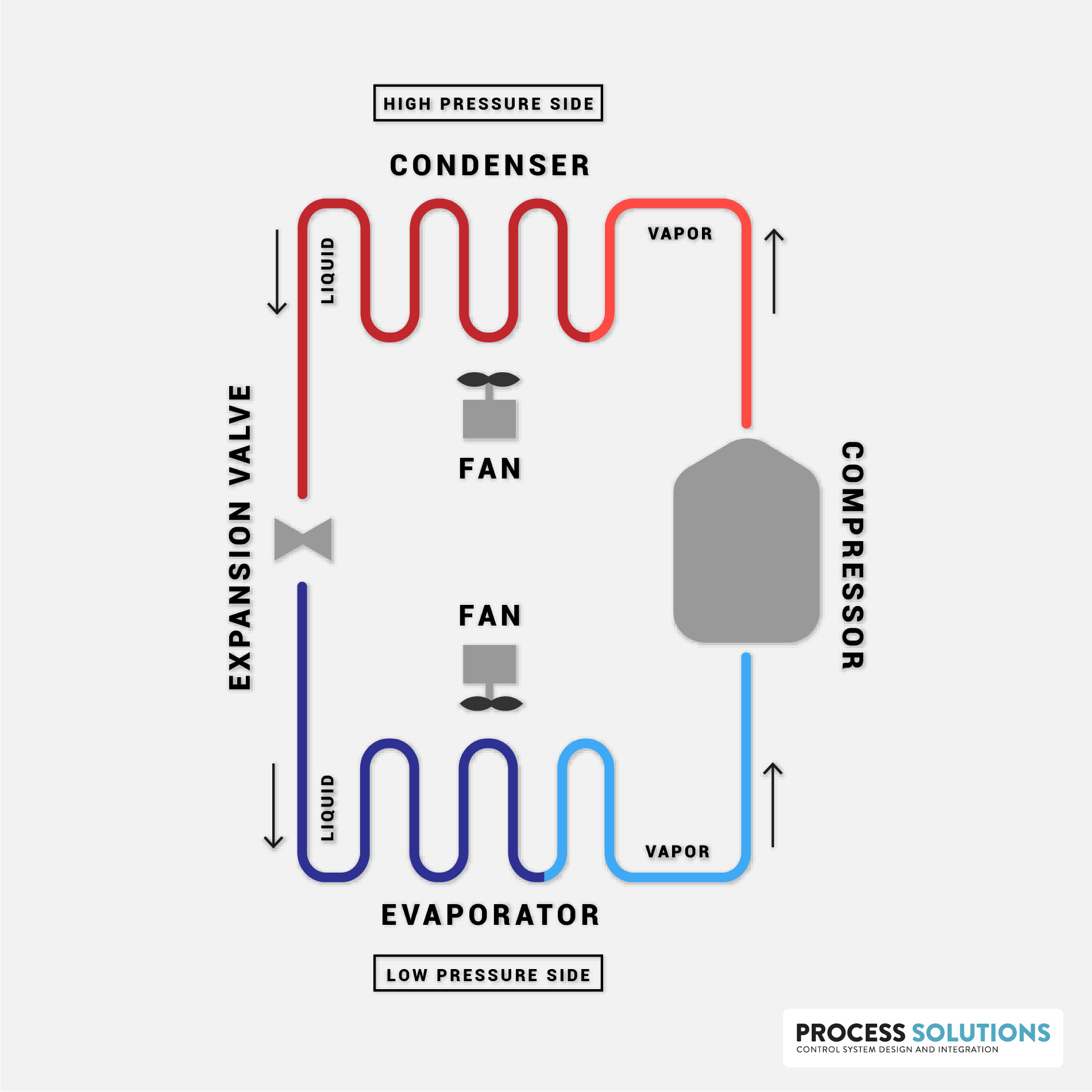
How Does a Compression Refrigeration System Work? | Process ...
Thermodynamic Analysis of Vapor Compression Refrigeration Cycle

Refrigeration Cycles Chapter 11: ERT 206/4 THERMODYNAMICS ...
Lab #8 Refrigeration
ANN approach for irreversibility analysis of vapor ...

Refrigerator – Team C
Module 128: Improving the performance of vapour compression ...
Ph diagram for a vapour compression cycle | Physics Forums

Vapour Compression Refrigeration System (VCRS) - Components ...

Schematic diagram for the ideal vapor-compression ...
Vapor Compression System | Compression Cycle | ARANER

The Ideal Vapor-Compression Refrigeration Cycle A ...

P-h diagram of vapor compression refrigeration cycle ...
Ch10, Lesson B, Page 4 - Non-Ideal Vapor-Compression ...

Chapter 4c: First Law - Refrigerators (Updated 3/13/2013)


Comments
Post a Comment