41 current sensing relay circuit diagram
load sensing circuit/relay | Forum for Electronics 1. Activity points. 69. I have been digging through various forums and internet articles searching for a current sensing relay circuit that will activate a low voltage relay when the circuit senses a 120v machine drawing 5 or more amps of power. I have hand drawn a schematic and is attached. My desire is to activate a low voltage circuit by ... AN-105: Current Sense Circuit Collection Making Sense of ... AN-105: Current Sense Circuit Collection Making Sense of Current. by Tim Regan, Jon Munson, and Greg Zimmer Download PDF Introduction. Sensing and/or controlling current flow is a fundamental requirement in many electronics systems, and the techniques to do so are as diverse as the applications themselves.
Ir Sensor Circuit Diagram Pdf - U Wiring Ir sensor circuit diagram pdf. Fig 1 Block Diagram of water tank level monitoring and pump control system. 5 Complete circuit diagram of th e system. Since the output pin is 33V TTL logic it can be used with any platforms like Arduino Raspberry PIC ARM 8051 etc. The sensor was evaluated.
Current sensing relay circuit diagram
PDF Current Sensing Circuit Concepts and Fundamentals Current Sensing Circuit Concepts and Fundamentals. AN1332 DS01332B-page 2 2010-2011 Microchip Technology Inc. Selection Criteria The disadvantages mentioned previously could be reduced by using low-value sensing resistors. However, the voltage drop across the sensing resistor Current sensing relay - Electrical Engineering Stack Exchange I have a 240v/30a table saw and want to automatically start my dust collector, 240v/20a by means of a current sensing switch and relay. I have a 30a double pole relay w/ 24v coil. A 24v transformer 40va, and a Dwyer series ccs current switch, amprage sensing range 0 -200a ac, switch rating 1a @ 240 vac. Relay Wiring Diagram: A Complete Tutorial | EdrawMax The diagram above is the 5 pin relay wiring diagram. There are different kinds of relays for different purposes. It can be used for various switching. Relay can be the best option to control electrical devices automatically. 5 pin is compromised of 3 main pins and an SPDT (single pole double throw).
Current sensing relay circuit diagram. The current-sensing relay in this water pump electrical circuit prevents the pump from running when the water level is too low. When a pump is operated with a flooded suction and liquid completely covers its inlet, the pump's motor will draw normal operating current. On the other hand, if the liquid level falls below the inlet, the pump's ... Simplifying Current Sensing (Rev. A) - Texas Instruments exhaustive list of all current-sensing challenges and TI application notes, but it does address many of the more common and challenging functional circuits seen today. If you have any questions about the topics covered here or any other current-sensing questions, submit them to the Amplifier forum on TI's E2E™ Community. Voltage Monitoring Relay Circuit Diagram - U Wiring A current sensing device requires the motor. 3-30 V 6-60 V 30-300 V and 60-600 V. 12 Volt Dc Reversing Solenoid Continuous Duty Relays 12 Volt 24 Volt Dc Power Relays Electronic Circuit Design Relay Electronic Circuit Projects 025 in male quick connect. Voltage monitoring relay circuit diagram. Philips IC Type TEA 104 1T is […] 3 Simple Proximity Sensor Circuits 3. Op-amp (IC LM358): Op-amp or operational amplifier is a multi-purpose ic and is highly revered in the electronics world. In this project op-amp is used as a comparator. LM358 IC has two op-amps which means we can make two proximity detectors using just one IC. The reason to use op-amp in the circuit is to convert analog signal into digital ...
AC Relay Power Switch Circuit - ElectroSchematics.com It utilizes a current transformer, single transistor amplifier, voltage doubler detector, robust relay and capacitor limited AC power source. Schematic of the AC Relay Switch Circuit. Current transformer. The current transformer came out of my junk box - it has unknown specifications other than its turns ratio (1000:1) that I measured. Interfacing ACS712 Current Sensor with Arduino - Measure ... The screw terminals of the ASC712 Current Sensor Module board are connected in series with the motor and power supply as shown in the circuit diagram. Then connect the VCC, GND and OUT of the ASC712 board to +5V, GND and A0 of Arduino. Now, in order to view the results, a 16×2 LCD is connected to Arduino. How to Build a Current Sensor Circuit A current sensor circuit is a circuit that can measure the current flowing through it. Current sensor circuits are used extensively in systems such as battery management systems in order to detect the current to monitor for overcurrent, a short circuit, and the state of charge of the battery system. PDF Installation Instructions for Models 50 and 51 Current ... Current Sensing Relay or its connected load. 3. Follow all local electrical and safety codes, the National Electrical Code (NEC), and OSHA requirements. HUMIDIFIER MODEL 50 CURRENT SENSING RELAY METAL BRACKET COMMON LEAD FURNACE BLOWER MOTOR COMMON 24 120 VAC VAC TRANSFORMER R C A B ODT CfW/G H FURNACE BLOWER MOTOR MODEL 50 HUMIDIFIER AUTOMATIC ...
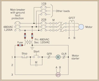
MOTOR CIRCUITS AND CONTROL – Applied Industrial Electricity A contactor is a large relay, usually used to switch current to an electric motor or another high-power load.; Large electric motors can be protected from overcurrent damage through the use of overload heaters and overload contacts.If the series-connected heaters get too hot from excessive current, the normally-closed overload contact will open, de-energizing the contactor … How to Connect Relay | Relays Working Principle - Circuits ... You could connect the LDR circuit to the input circuit of a relay via relay driver. When a small current from sensor flow through this circuit, the relay will activate its output circuit, allowing a much bigger current to flow. Thus turning ON the electrical bulb. Relay Connection Diagram and Connection Procedure Current Sensing Circuit : 5 Steps - Instructables Ways to measure current: 1- Indirect method: such as current transformers (in the figure) and Hall effect sensors, which relies on Faraday's law of induction to sense current in a circuit and convert it to a proportional voltage. These methods are suitable more for high current systems. 2- Direct method: which relies on Ohm's law which states that V = I x R. Linear Hall-Effect Sensor - Homemade Circuit Projects Circuit Diagram using Hall Effect Sensor. ... However, when the relay switches, the current will be removed which will prompt the relay to switch again, and this may cause rapid chattering of the relay at the thresholds. To avoid this, a latching feedback will be necessary. Also make sure to add a 47uF/25V capacitor across base/emitter of the ...
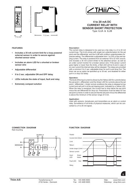
4 to 20 mA DC CURRENT RELAY WITH SENSOR ... - Thiim A/S
Over load monitoring and Protection using Arduino & ACS712 ... This is the complete circuit diagram of the over load monitoring system, this schematic is designed in cadsoft eagle 9.1.0 version. If you want to learn how to make schematics and pcb's then watch my tutorial. This is the ACS712 Current sensor, the vcc is connected with the Arduino's 5v, the ground is connected with the Arduino's ground ...
Results page 313, about 'Stereo PLL AM transmitter ...
Current Sensing Relay Wiring Diagram Gallery - Wiring ... Source: morningstarcorp.com. Size: 72.00 KB. Dimension: 654 x 493. DOWNLOAD. Wiring Diagram Sheets Detail: Name: current sensing relay wiring diagram - current sensing relay circuit diagram best of i2c relay control rh nawandihalabja 12V Relay Wiring. File Type: JPG.
Electrical wiring diagram. sensor, load current sensor and ...
Current Sensing Techniques - Circuit Digest During the current sensing process, the current is measured by measuring the magnetic field. The output voltage is very low and needs to be amplified to a useful value by using a high gain amplifier with very low noise. Apart from amplifier circuit Hall Effect sensor requires additional circuitry as it is a linear transducer.

Normally Closed Current Sensors - Functional Devices, Inc.
Temperature Sensor Relay Switch Circuit - circuits-diy.com 6,410 views. Today we are going to demonstrate a project of a Temperature sensor relay switch circuit. This is just like a normal heat or temperature sensor with a relay so whenever the circuit will receive heat the relay will activate and so will the load or device connected to the relay. Any AC 110V or 220V or DC appliance can be connected to ...
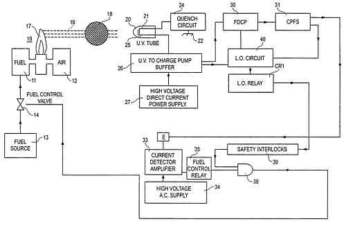
Flame Detector Circuit
CR4395 AC Current Sensing Relay - CR Magnetics The CR4395 series Current Sensing Relay provides an effective and highly stable method for monitoring electrical current. The current-carrying wire is routed through the opening extending from the top of the case. When current reaches the level set by the trip point adjustment, the relay trips and starts the adjustable timer.

resideo 32001754-001 Current Sensing Relay Installation Guide ...
Current Circuit Diagram - Wiring Sample Current circuit diagram. The coil of the latching relay consumes power only while the relay is switched ON. The photodiode absorbs energy from light and releases electrons thereby acting as an input current source. Crowbar Circuit Diagram. And its contact remains in position after the switch has been released.

Light Sensor Switch Circuit
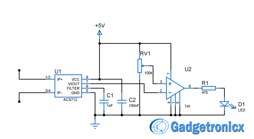
Current sensor switch circuit - Gadgetronicx Current sensors are used when there is a need to measure the amount of current consumed by a certain appliance or device. There are several methods to measure the current flow and we are about to use Hall effect in our Current sensor switch circuit. IC ACS712 a simple linear current sensor form the most significant part of this circuit.

How To Hook Up a Digital Magnetic Sensor to a Relay | Sensor ...
Current Sensing Switch, Normally Open Current Sensing ... Typical Wiring Diagram; ... Disconnect all power supplies in the circuit, and fix the AC current sensor switch in a proper position through the mounting hole of the base. If you use screws to install, make sure to tighten each screw. ... CR Magnetics CR4395-EH-120-101-A-CD-ELR-I Current Sensing Relay with Internal Transformer, 120 VAC ...

LM741 Light Sensor Relay Switch
Current Sensing Switches (Current Sensing Relays) | NK ... SENSING APERTURE. ATS SERIES - SWITCH SETPOINT. Switch Selectable 10-1200 A. Electromechanical SPDT Relay, Plus 4 - 20 mA. 120 VAC or 24 VDC. 1.875" dia. ATS SERIES - DIGITAL SETPOINT. Switch Adjustment 1-50 A or 4-200 A (depending on model) Isolated Solid-State Relay, 1.0 A Max Plus 4-20 mA, 0-5 VDC or 0-10 VDC.
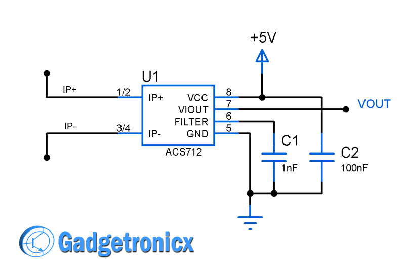
Current sensor switch circuit - Gadgetronicx
Difference between earth leakage relay and earth fault relay Difference between earth leakage relay and earth fault relay Earth fault is an undesirable condition at which current flow from a conductor to earth. This can happen when a current-carrying conductor falls on the ground or the body of any equipment or when someone touches a live conductor with adequate PPE or due to insulation failures.

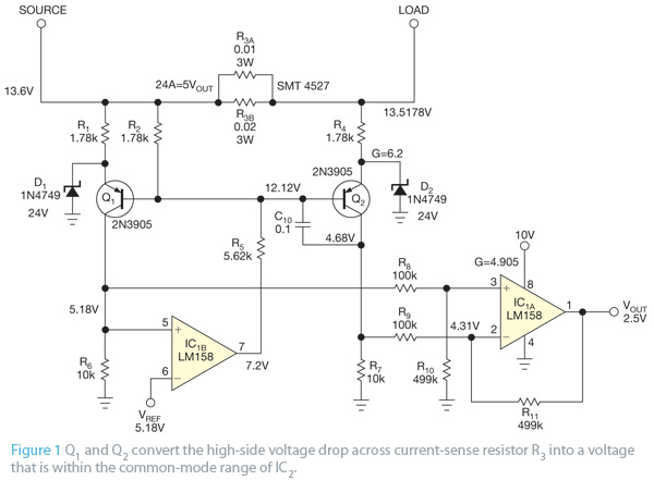
AN-105: Current Sense Circuit Collection Making Sense of ...
Time Delay Relay Basics: Relay Circuit and Applications Introduction. Time relay refers to a kind of relay whose output circuit needs to make an obvious change (or contact action) after adding (or removing) the input action signal in a specified and accurate time. It is an electrical component used in a circuit with a lower voltage or a smaller current to switch on or off a circuit with a higher voltage and larger current.

Earth Leakage Relay Wiring and Connection Diagram - ETechnoG
Simple Relay Switch Circuit Diagram Working of the Basic 5V Relay Circuit. In the above circuit, 5V relay is powered by a 9V battery. An ON/OFF switch is added for the switching purpose of the relay. At the initial condition when switch is open, no current flow through coil, hence Common Port of relay is connected to NO (Normally Open) Pin, so the LAMP remain off.

The Basics of Current-Sensing Relays | EC&M
Relay and Relay Circuits Schematic Circuit Diagram Door Circuits: Various door circuits can be made by controlling the current flow with the relays. The example circuits are given below. The example circuits are given below. In the three relays given in Figure 1.10, if the bobbins are energized, they will draw their pallets to them and the current at the output will reach the current.

Humidity Sensor Circuit
Relay Wiring Diagram: A Complete Tutorial | EdrawMax The diagram above is the 5 pin relay wiring diagram. There are different kinds of relays for different purposes. It can be used for various switching. Relay can be the best option to control electrical devices automatically. 5 pin is compromised of 3 main pins and an SPDT (single pole double throw).

HVAC Current Sensing Relay Operation and Troubleshooting!
Current sensing relay - Electrical Engineering Stack Exchange I have a 240v/30a table saw and want to automatically start my dust collector, 240v/20a by means of a current sensing switch and relay. I have a 30a double pole relay w/ 24v coil. A 24v transformer 40va, and a Dwyer series ccs current switch, amprage sensing range 0 -200a ac, switch rating 1a @ 240 vac.
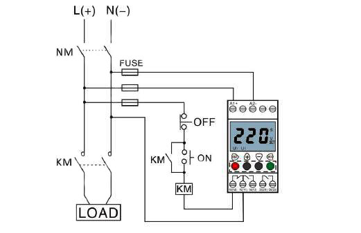
Voltage Monitoring Relay, Under/Over Voltage, 1 Phase, 110 ...
PDF Current Sensing Circuit Concepts and Fundamentals Current Sensing Circuit Concepts and Fundamentals. AN1332 DS01332B-page 2 2010-2011 Microchip Technology Inc. Selection Criteria The disadvantages mentioned previously could be reduced by using low-value sensing resistors. However, the voltage drop across the sensing resistor
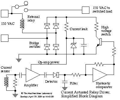
Current Actuated Relay Driver
The Basics of Current-Sensing Relays | EC&M

Electrical Relay and Solid State Relays for Switching

Macromatic CAH05A6AJ 0.5-5A 12V Current Sensing Relay
Current sensor switch circuit - Gadgetronicx

Can I use the SIM100 to tell whether a bulb is burnt out ...

Relay Switch Circuit and Relay Switching Circuit

Free Shipping GEYA GRI8 01 Current Monitoring Relay Current ...
Precision Current Sensing and Monitoring Circuit using IC ...

Aprilaire 51 Current Sensing Relay 120 Volt

Short circuit detector (autoreverser circuit) using current ...
Current Sensing Theory - NK Technologies

Control Relay 】 What is a Control Relay?

Residual Current Circuit Breaker | Electrical4U
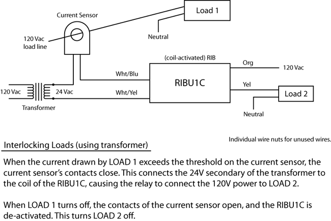
How do I interlock loads with a transformer, current sensor ...

Temperature Sensor Relay Switch Circuit

Amazon.com: Current Sensing Switch, Normally Open Current ...

Latching Relay: What is it? (Circuit Diagram And How it Works ...
Using smart relay drivers for smart meters, part 1 ...

Ice Breaker: Troubleshooting Current Relays | 2012-09-03 ...

Low Current Triggered Relay using 2n3904 Transistors

Current Sensing Slave Power Switch using Relay

AN-105: Current Sense Circuit Collection Making Sense of ...

Using Current Transformers with Current Sensing Relays
Results page 110, about 'rated current'. Searching circuits ...


Comments
Post a Comment