40 paragon defrost timer wiring diagram
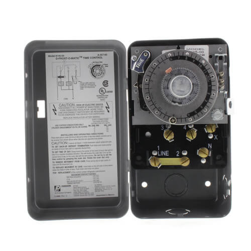
PDF 8000 MECHANICAL Series DEFROST TIMER - Everwell Parts 2. Set Defrost Insert pin(s) to desired defrost time(s) on outer dial. 3. Set Defrost Duration Move copper pointer to desired duration of defrost time on inner dial. Install our Commercial Defrost Controls today to understand why Paragon® is Simply the Right Choice™ in Defrost Timers. An ISO 9001 - 2008 Certified Company 1 Year Limited ... Paragon Defrost Timer 8145 20 Wiring Diagram Jan 12, 2018 · Find solutions to your paragon defrost timer 20 wiring diagram question. Get free help, tips & support from top experts on paragon defrost timer Adjustable Defrost Cycle Duration: 4 to minutes in S and Paragon Wiring Diagrams Electric Heat Defrosting S & S Series. how to test paragon 20 defrost timer rh waterheatertimer org Paragon 20 Wiring Schematic Paragon Time Clock tors, Paragon ...
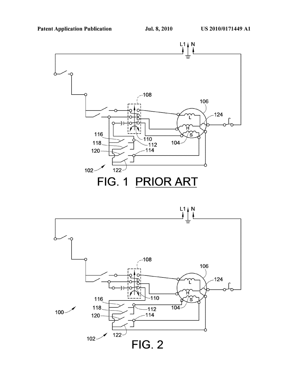
Paragon 8143 20 Wiring Diagram - schematron.org Paragon 00 Wiring Diagram Timer 20 Somurich 1 On Defrost Image Info File Name: schematron.org Jun 20, · Basically the jumper between 2 and 3 was schematron.org #4 and X were jumpered schematron.org feed was from X to #4,#2 and to the schematron.org the other side one leg to the C/U was broken from #3 to N terminal.I found it schematron.org god ...

Paragon defrost timer wiring diagram
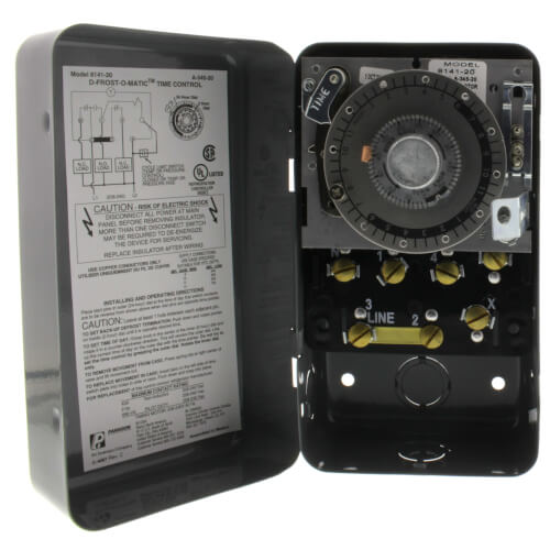
Paragon Defrost Timer 8141-20 Wiring Diagram Mar 03, 2019 · Paragon Defrost Timer 8141-20 Wiring Diagram. Paragon - /V Defrost Timer - Designed for commercial freezers and refrigerators, Paragon commercial defrost controls provide. How to test Paragon defrost timer. Timer dial rotates continuously, and keeps good time. X Trippers are attached to edge of dial. When. Paragon time clock 8145-20 manual - Co-production ... Why Choose Paragon® Defrost Timers? 8145-20. Electric Heat,. Hot Gas or Compressor Shutdown. Closed. Open. None Initiate 15 minute manual defrost. Mar 18, 2018 - Paragon defrost timer 8145 20 wiring diagram intermatic defrost timers and manuals. Zoom out/reset put photo at full zoom then double click. T101 24 hour timer Have a manual for ... Paragon 8141-20 - 208/240V Defrost Timer - SupplyHouse.com Paragon 8141-20 - 208/240V Defrost Timer - Designed for commercial freezers and refrigerators, Paragon commercial defrost controls provide automatic defrost capability. They accommodate various types of defrost systems including electric defrost heaters, hot gas and compressor off cycle. Time initiated, temperature or pressure terminated High ...
Paragon defrost timer wiring diagram. Paragon 8145 00 Wiring Diagram - easywiring Paragon defrost timer 8145 20 wiring diagram paragon defrost timer wiring furthermore paragon defrost timer 8145 rh beinclover co. Here is a picture gallery about 20 wiring diagram complete with the description of the image please find the image you need. Wiring diagram sheets detail. Models 8143 00 and 8143 20 wiring. PDF Paragon 8045-20 defrost timer wiring diagram Paragon 8045-20 defrost timer wiring diagram Tap image to zoom. Roll over image to zoom. Paragon 8040 series defrost timer Defrost frequency is one to six cycles per day Adjustable back up defrost termination from 4 - 110 minutes (2 minute increments) Time initiated/time terminated Choice of three contact arrangements for electric heat, 8145 20 Timer Wiring Diagram Description: Paragon Defrost Timer Wiring Diagram Paragon Defrost Timer Wiring regarding 20 Wiring Diagram, image size X px, and to view image details please click the image. Here is a picture gallery about 20 wiring diagram complete with the description of the image, please find the image you need. Paragon Defrost Timer 8145-00 Wiring Diagram Dec 09, 2018 · Then timer outputs can control 3-phase power using 3-phase contactors Contactor below is 3 phase with V coil http: Link below is for Paragon commercial box-type defrost timers http: I cant seem to find a wiring diagram on how to wire this correctly Link below has wiring diagrams and wiring manuals for V http: According to information from ...
Paragon 8145 20 Defrost Timer Wiring Diagram - easywiring Paragon 8145 20 defrost timer wiring diagram. It reveals the elements of the circuit as simplified forms and also the power and also signal connections between the tools. Collection of paragon defrost timer 8145 20 wiring diagram. 8047 20 208 240 for electric heat defrosting auxiliary contact models 50 hz available open open closed 4 110 min. Paragon 8145 20 Defrost Timer Wiring Diagram Oct 12, 2018 · on Paragon 8145 20 Defrost Timer Wiring Diagram. Adjustable Defrost Cycle Duration: 4 to minutes in S and Paragon Wiring Diagrams Electric Heat Defrosting S & S Series. tors, Paragon® Commercial Defrost Controls Choice TM in Defrost Timers. SLINE 2. Timer Wiring Diagram Manual - Wiring Diagram and Schematic ... Tork Rz307 Timers Digital Lighting Timer Guide Manualzz. Hager Eh 010 Timer Instruction Manual Manualslib. 2510sxt Wiring Diagram Hydrotech Sxt Timer User Manual Page 20 24 Original Mode. Paragon 632 20 Defrost Timer. Eapl Model A1d1 On Power Application Preset Timing Starts And At. Clock Timer Wiring Diagram And Setting Home Appliances Parts ... Paragon 8141-00 Wiring Diagram Grasslin Defrost Timer Wiring Diagram Best Image rhdiagramoceanodigitalus along with Paragon Timer Wiring Diagram And Whirlpool From Rhfharatesinfo or Paragon Timer 20 Wiring Diagram Free Download \u Playapkcorhplayapkco in addition Paragon Timer Wiring Diagram In Addition To Sell Sheet With Rhfharatesinfo further Paragon Timer Defrost Wiring ...
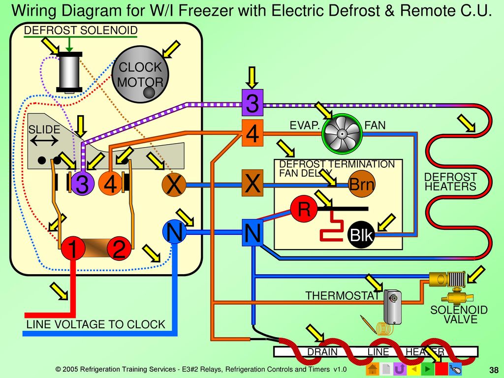
Paragon Timer Wiring Diagram For Freezer - Wire Paragon sell sheet shows model numbers and wirings diagrams replace with tt or ct series. Walk in freezer defrost timer wiring diagram wiring diagram is a simplified suitable pictorial representation of an electrical circuit it shows the components of the circuit as simplified shapes and the skill and signal associates together with the devices. Paragon Timer Wiring Diagram - schematron.org Sep 12, 2018 · The Paragon® Series Auto Voltage Defrost Timer is designed competitive voltage-specific mechanical defrost timers, eliminating Wiring Diagrams. Simple wiring. Resources: Paragon sell sheet shows model numbers and wirings diagrams, Replace with TT or CT series. Paragon 8141 00 Wiring Diagram Download - Wiring Diagram ... Dimension: 645 x 471. DOWNLOAD. Wiring Diagram Images Detail: Name: paragon 8141 00 wiring diagram - Paragon Timer Wiring Diagram Diagrams Schematics Throughout Defrost Time Clock 0. File Type: JPG. Source: natebird.me. Size: 193.58 KB. Dimension: 1659 x 891. Typical wiring for defrost on a single evaporator freezer ... Wiring for a single evap freezer system or reach in freezer. Any questions or comments Feel free to ask in the comment section . Thanks for watching 👍. ...
Appliance411 FAQ: How does a Frost Free Refrigerator's ...
8141-00 Defrost Timer Wiring Diagram Paragon 00 Wiring Diagram Defrost Timer Circuit Evaporator. The Paragon® Series Auto Voltage Defrost Timer is designed for commercial freezers Wiring Diagrams. AV. AV Heavy-duty steel case with electrical knockouts in the sides, Specifications. Operating Voltages: or / VAC, 60 Hz HEATER.
Defrost Time Controls / HVAC/R Defrost Time Controls / HV AC/R
Whirlpool Refrigerator Defrost Timer Wiring Diagram ... Whirlpool Gold Refrigerator Diagram. Whirlpool Refrigerator Water Line Diagram. 3 Wire Defrost Termination Switch Wiring Diagram. Lg Inverter Refrigerator Wiring Diagram. Ge Monogram Refrigerator Wiring Diagram. Ge Refrigerator Wiring Diagram Problem. 8 Pin Timer Relay Wiring Diagram. Whirlpool Gas Dryer Wiring Diagram.
208/240V Defrost Timer
Paragon Defrost Timer 8141-20 Wiring Diagram Oct 23, 2018 · The Latest Paragon® Defrost Timer • Universal Defrost Timers (UDT) Universal Defrost Timer – Wiring. Convert to Convert to Convert to N 1 4 32 X. Jun 20, · They are both commercial as well. I know when we draw up the schematic diagram the position of N and X are different.
Paragon 4001-0G Defrost Timer: Wall Timer Switches: Amazon ...
Grasslin Dtav40 Wiring Diagram Grasslin Dtav40 Wiring Diagram. For electric heat, hot gas or compressor shutdown defrost. The Grässlin DTAV40 Series Auto Voltage Defrost Timer is applicable to air defrost (compressor. Intermatic/Grässlin's Defrost controls just got even better! The DTAV40 defrost control automatically selects the appropriate voltage between Wiring Diagrams .

China Defrost Timer, Defrost Timer Wholesale, Manufacturers ...
8145 20 Wiring Diagram - easywiring A diagram showing how to switch wires from. 6 days ago november 22nd i have a paragon 20 defrost timer do you wire the compressor to the timer i cant seem to find a wiring diagram on. Here is a picture gallery about 8145 20 wiring diagram complete with the description of the image please find the image you need.

No frost | D-frost Timer Diagram - FULLY4WORLD
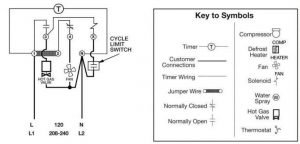
Grasslin Defrost Timer Wiring Diagram The DTSX Defrost Timer is identical in function, terminal identifi- cation, and wiring to the Paragon and Precision series Defrost Timers. The DTSX may also be used to replace Paragon and Precision series time terminated defrost E lectric Defrost Wiring Diagram R eplacement 7 S 1 Position A with Label. For electric heat, hot gas or compressor ...

Precision Multiple Controls Official Website - Your Source ...
483212 defrost timer wiring - Appliance Repair Forum ... Joined: 11/5/2011 (UTC) Posts: 2. The part replacement for the defrost timer has a black wire that was not on the original part. I have confiremd that this is a replacement but the are options for the black wire depending up the original wiring diagram of the unit. I chose version2/procedure 3 as it seemed to fit.
AUTO VOLTAGE DEFROST TIMERS 8000 SERIES
PDF Paragon digital defrost timer wiring diagram - Weebly Paragon digital defrost timer wiring diagram UDT - Universal Defrost Timer Universal Defrost Timer (UDT) The Universal Defrost Timer family consists of two models: electric defrost and off-cycle defrost. Both models can be wired directly to 120V AC, 208V AC or 240V AC power sources. The timers can be used in place of traditional ...
E3 HVACR Controls and Devices - ppt download
Paragon Defrost Timer 8141 00 Wiring - Wiring Diagrams If not, probably the wiring is backwards. They generally are good timers. If it has, you may have. how to wire model defrost timer - Paragon Defrost Timer Changing the defrost timer will not require use of a wiring diagram. Results 1 - 37 of 37 The Paragon® Series Auto Voltage Defrost Timer is designed for commercial freezers and refrigerators ...

I have an 8141 Paragon defrost timer and have to replace it ...
Paragon Defrost Timer 8145 20 Wiring Diagram Gallery Collection of paragon defrost timer 8145 20 wiring diagram. A wiring diagram is a simplified traditional photographic depiction of an electrical circuit. It reveals the elements of the circuit as streamlined shapes, and also the power as well as signal links in between the tools.
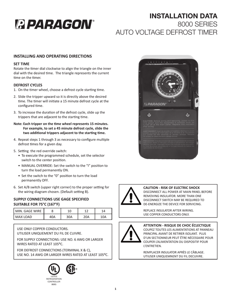
INSTALLATION DATA 8000 SERIES AUTO VOLTAGE DEFROST TIMER
Paragon 8141-20 - 208/240V Defrost Timer - SupplyHouse.com Paragon 8141-20 - 208/240V Defrost Timer - Designed for commercial freezers and refrigerators, Paragon commercial defrost controls provide automatic defrost capability. They accommodate various types of defrost systems including electric defrost heaters, hot gas and compressor off cycle. Time initiated, temperature or pressure terminated High ...

Electrical Engineering Topics: March 2021
Paragon time clock 8145-20 manual - Co-production ... Why Choose Paragon® Defrost Timers? 8145-20. Electric Heat,. Hot Gas or Compressor Shutdown. Closed. Open. None Initiate 15 minute manual defrost. Mar 18, 2018 - Paragon defrost timer 8145 20 wiring diagram intermatic defrost timers and manuals. Zoom out/reset put photo at full zoom then double click. T101 24 hour timer Have a manual for ...
120V Defrost Timer
Paragon Defrost Timer 8141-20 Wiring Diagram Mar 03, 2019 · Paragon Defrost Timer 8141-20 Wiring Diagram. Paragon - /V Defrost Timer - Designed for commercial freezers and refrigerators, Paragon commercial defrost controls provide. How to test Paragon defrost timer. Timer dial rotates continuously, and keeps good time. X Trippers are attached to edge of dial. When.

SOLVED: How do i wire a Paragon 4001-00 timer? - Fixya

Paragon Defrost Timer 8hr 7min for Refrigerator units
Defrost Timer Control, 120/208/240V AC Voltage, 30 A Amps, 1 SPDT, 1 SPST
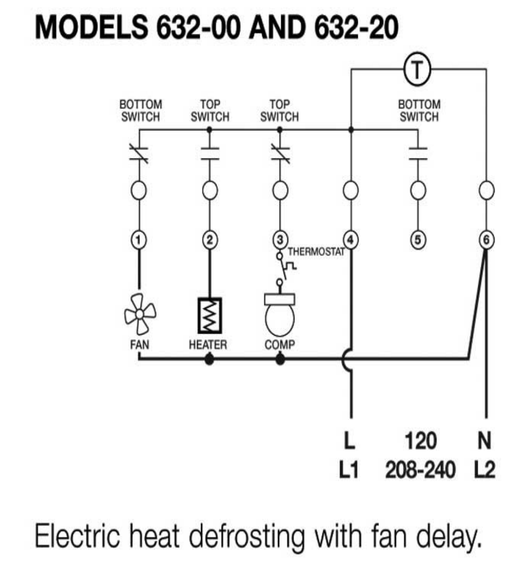
Paragon 632 20 defrost timer
MECHANICAL DEFROST TIMER 8000 Series
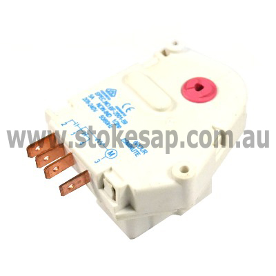
REFRIGERATOR UNIVERSAL DEFROST TIMER 6 HOURS 21 MINUTES PARAGON
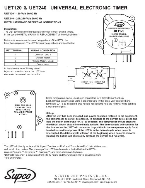
Installation & Operating Instructions - Supco

HOW FREEZER DEFROST TIMER OPERATES - PART 2
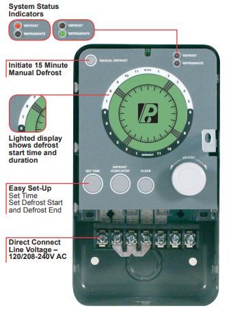
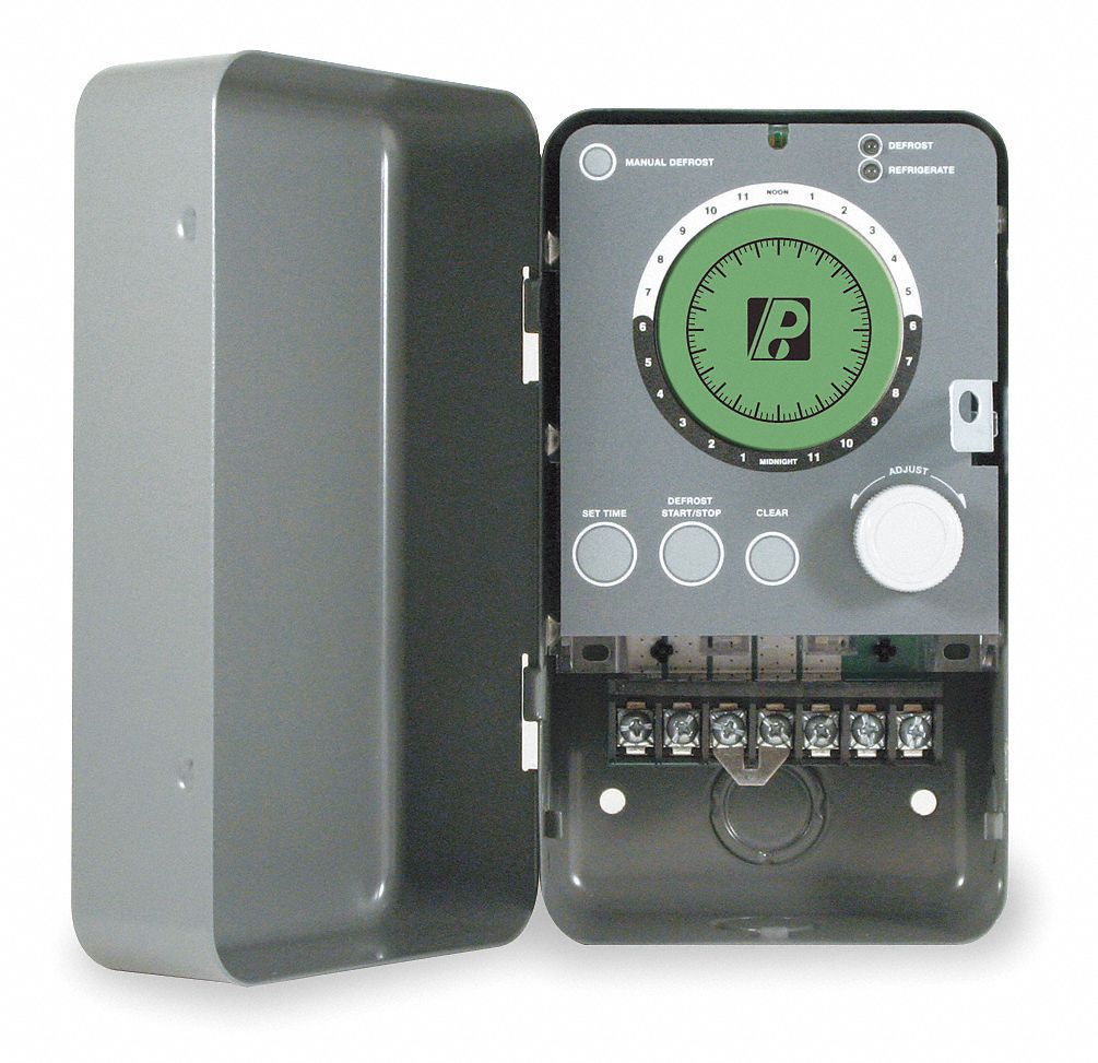
PARAGON COMMERCIAL DEFROST TIMER DIGITAL
AUTO VOLTAGE DEFROST TIMERS 8000 SERIES
TABLE OF CONTENTS

Fisher & Paykel Westinghouse Fridge Defrost Timer for 6hr 21min - 1458327
REFRIGERATION
INSTALLATION DATA 8000 SERIES AUTO VOLTAGE DEFROST TIMER
Robertshaw 8000 Series Auto Voltage Defrost Timer manual ...
Defrost Timer DBZC-625-1G1 @ Timer Peti Ais 625 825 DBZC825 Timer 825 @ Paragon Timer @ 825 Timer 625 Timer
UNIVERSAL DEFROST TIMERS 9145 / 9045 Series
Washing Machine Wiring to Reduce Mechanical Timer Contact ...
Part Number: E104282_P

I have an 8141 Paragon defrost timer and have to replace it ...
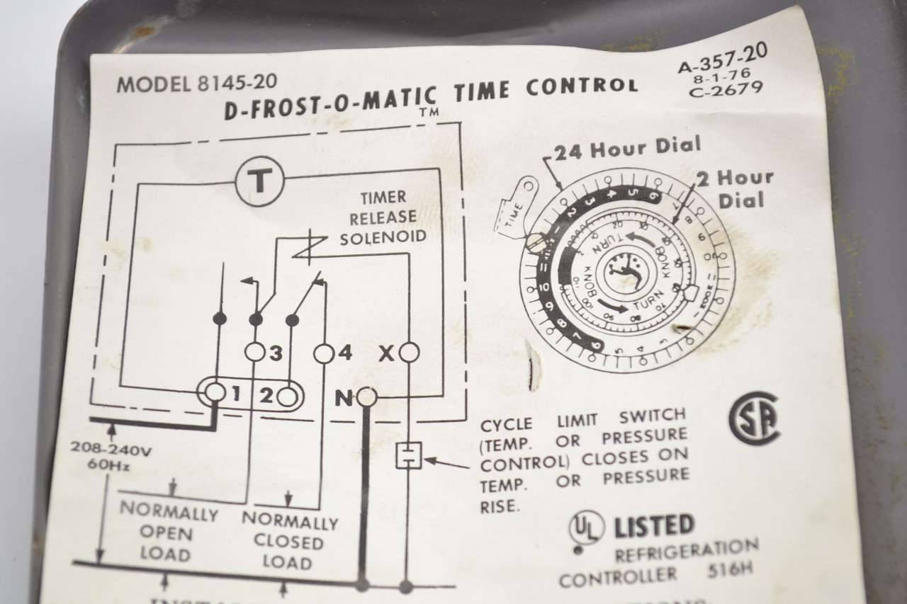
Paragon 8145-20 D-frost-o-maic Time Control Defrost 208-240v ...

SOLVED: Paragon 8141-00 defrost timer wont turn. - Fixya

Typical wiring for defrost on a single evaporator freezer
Operating Instructions
Defrost Archives - HVAC School
REFRIGERATION

Paragon 8145-20 Defrost Timer for Commecial Refrigeration 220V | eBay


Comments
Post a Comment