40 flex a lite wiring diagram
beb.pisa.itPasiones Novelas Turcas [MFIQVY] Feb 20, 2022 · Search: Pasiones Novelas Turcas. Además valoran la importancia del diálogo gestual Ali está casado con Cemile y tienen cuatro hijos Cuando la pasión espera Cada año la cadena hace reposiciones de producciones que ya han sido estrenadas anteriormente, por lo que solamente se encuentra en esta lista la fecha de su primera emisión 607 of title 47 of the code of federal regulations, all ... PDF Installation Instructions - Summit Racing Equipment WIRING DIAGRAM - MODEL 430 (PUSHER) 3A. Connect the fan wires to the VSC (Model 410 puller fan only) Now begin wiring the motors to the VSC. Using the large butt connectors provided, connect the red wire ... Flex-a-lite Consolidated, 7213-45th St. Ct. E. Fife, WA 98424, Telephone No. 253-922-2700, warrants to the original purchasing user, that ...
Flex a lite wiring diagram
PDF Part number 31149 Temp. Control Module - Flex-a-Lite Wiring Diagram 1a. Connect the motor wires to the control module (Red wire to the "M+" terminal and black wire to the "M-" terminal). 1b. Disconnect the negative battery lead for safety while finishing the wiring. Use the large diameter red (10 AWG) wire to run power directly from the battery positive (+) terminal to the "B" terminal on the control module. PDF 4-PIN COMPACT FLUORESCENT LAMPS INSTALLATION ... - Emergi-Lite 1.b) flex conduit wiring diagram: 2.a) flex conduit wiring diagram: inverter connector violet+ brown-white red a ballast ac lamp 1 lamp 2 c om n unswitched hot black 120v or orange 2 7v (c apunused lead) wall switch wht/blk blue blu/wht red yellow yel/blk blue red blue red white white yellow yellow black b b a emergency ballast b. two (2) lamp ... › threads › 00-ram-1500-front00 Ram 1500, Front Driver Turn Signal Issues with 4x4 Light ... Feb 15, 2022 · I don’t have a wiring diagram handy, and I’m in the middle of a very heavy work week, but I’ll try to look when I have some time free. Just keep looking all over the sheet metal of the body, the frame, the battery ground terminal, the ground connections on the alternator, and the ground connections on the starter.
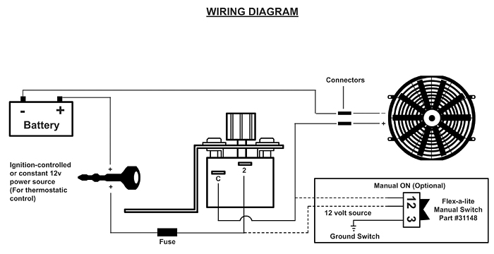
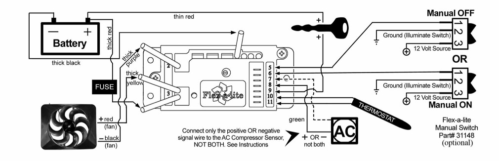
Flex a lite wiring diagram. PDF Suggested Electric Fan Wiring Diagrams - DaveBarton.com Suggested Electric Fan Wiring Diagrams Suggested Primary Cooling Fan - Single Speed (ON/OFF) Using 12 Volt Switching Devices Only for Primary Activation NOTE: Most stand-alone adjustable thermostats (i.e.: Hayden, Flex-a-Lite or Perma-Cool brands) can provide a 12 volt output when activated. Flex A Lite Electric Fan Wiring Diagram Gallery Assortment of flex a lite electric fan wiring diagram. A wiring diagram is a streamlined conventional photographic representation of an electric circuit. It reveals the components of the circuit as streamlined forms, and also the power as well as signal links in between the devices. Flex-a-lite Adjustable Electric Fan Controllers 31147 ... Dual electric fan (2 pages).View and Download Flex-a-Lite wiring diagram online. Temp. Fan Flex-a-Lite Installation Instructions. Adjustable temperature control kit (1 page) Fan Flex-a-Lite Installation Instructions. Variable speed control with screw-in temperature sensor (2 pages). Sep 21, · This Flex-a-lite controller turns the electric fan on and off according to the coolant temperature, and you can adjust where the fan turns on from approximately degrees F. PDF Part #330 Dual Electric Fan with Thermostatic Control and ... Step 8: (Optional) For manual switch operation, use Flex-a-lite p/n 31148. Connect the switch as shown on the wiring diagram (previous page). Connect the "M" terminal on the control module to the "#1" terminal on the switch. Connect the "#2" terminal on the switch to a positive 12v power source.
Flex A Lite Wiring Diagram Collection - mamvic.com Flex A Lite Wiring Diagram Effectively read a wiring diagram, one provides to know how the particular components inside the program operate. For instance , when a module will be powered up also it sends out a signal of fifty percent the voltage and the technician will not know this, he would think he provides an issue, as he would expect a new 12V signal. › showthreadAdvanced Bonsai Course - mobinuke.com Feb 21, 2022 · Students will learn advanced wiring techniques Students will become better bonsai artists after completing this course Requirements The students need to have completed the "Online Bonsai Course", which has the basic and intermediate content. Description Hector "Mulato" Melendez take your bonsai skills to the next level with this Advanced Bonsai ... Installation Instructions - Flex-a-Lite Installation Instructions. Temp. Control Module. Jeep Wrangler fan, 87-99 4 & 6 cyl. Direct-fit Lo-Profile S-Blade dual electric fan system with Variable Speed Controller for '72-'86 Jeep CJ. Direct-fit Flex-a-fit Aluminum Radiator and Electric Fan for '99-'12 Full-size GM Truck and SUV Applications. How to Install and Wire a Flex-a-lite Electric Fan Control ... How to Install and Wire a Flex-a-lite Electric Fan Control 31149 Tutorial Instructionshttp:// steel pro...
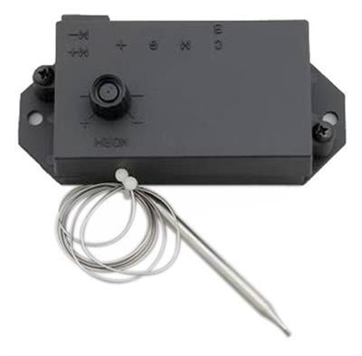
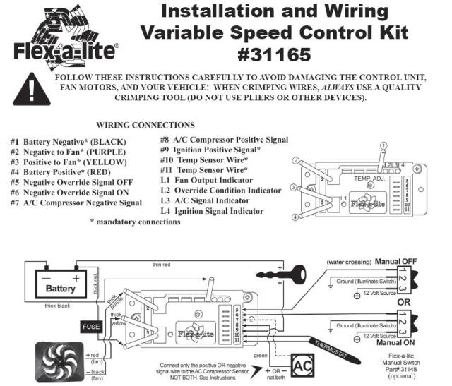
Flex A Lite Wiring Diagram For Vintage Air Trinary Switch On the flex-a-lite instructions #10, connect terminal 7 or 8 to wires going to A/C clutch. WIRING DIAGRAMS. Binary Switch / Trinary Switch COMPRESSOR DIMENSIONS. Sanden SD / SD-7B10 Compressors BUILD A SYSTEM WORKSHEET. Universal Fit Planner Vintage Air Goll St. San Antonio, TX P. F. How to Wire a Flex-a-lite Variable Speed Controller ... How to Wire a Flex-a-lite Variable Speed Controller Temperature Sensor 160-240 degrees 31163 33054 31165 31174 31173 ... PDF Replacement Adjustable Temperature Control Installation ... Step 7: (Optional) For manual switch operation, use Flex-a-lite p/n 31148. Connect the switch as shown on the wiring diagram (previous page). Connect the "M" terminal on the control module to the "1" termi-nal on the switch. Connect the "2" terminal on the switch to a positive 12v power source. Connect termi- PDF Emergency Ballast Wiring Guide THE EMERGENCY BALLAST WIRING GUIDE This Document has been customized to contain a wide library of individual dia-grams for various installation applications. If a diagram cannot be found within this selection, consult Customer Service. The diagrams are categorized primarily according to the number of lamps in the
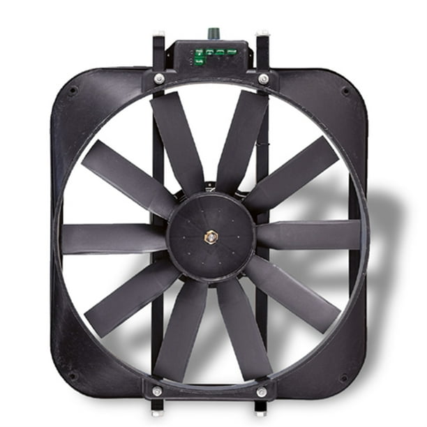
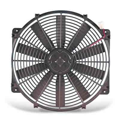
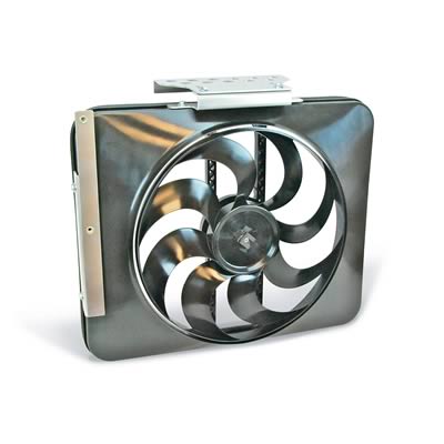
Flex-a-lite 30 Electra-Fan II Electric Fan - Walmart.com
Flex-a-Lite® - Trimline™ Electric Fan - CARiD.com Flex-a-lite® is a third-generation business that has been in the automotive industry for over half a century. In 1962, Eddy Davis, who was an Army Air Corps pilot in England during the Second World War, set up Flex-a-lite with the original 'flex fan' concept.
150 #99981
Cooling Fan Relay Wiring Diagram - Wiring Diagram 2003 - 2007 Cadillac Cts Fuses - Cooling Fan Relay Wiring Diagram. Wiring Diagram will come with several easy to adhere to Wiring Diagram Instructions. It really is meant to assist all of the typical user in creating a proper program. These directions will likely be easy to comprehend and apply. With this manual, you will be capable to ...
Electric Fan Switch with Thermostat, Adjustable
VA Trinary Switch wiring? - Pro-Touring.com In the diagram it shows one of the blue wires going to a relay post 86. And the electric fans spliced into it. Can I bipass this connection and run it directly to my Flex-a-lite wiring block? On the flex-a-lite instructions #10, connect terminal 7 or 8 to wires going to A/C clutch. It has the option of a pos. or neg. wire. Which would I use?
Flex-A-Lite Cooling Systems Installation Instructions
Flex A Lite Fan Controller Wiring Diagram - Wiring Diagram Flex A Lite Fan Controller Wiring Diagram - All Wiring Diagram - Flex A Lite Fan Controller Wiring Diagram Wiring Diagram contains several in depth illustrations that show the connection of assorted products. It contains directions and diagrams for various types of wiring techniques along with other items like lights, windows, etc.
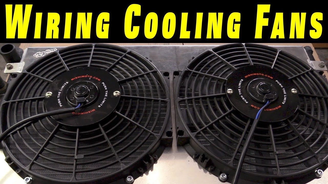
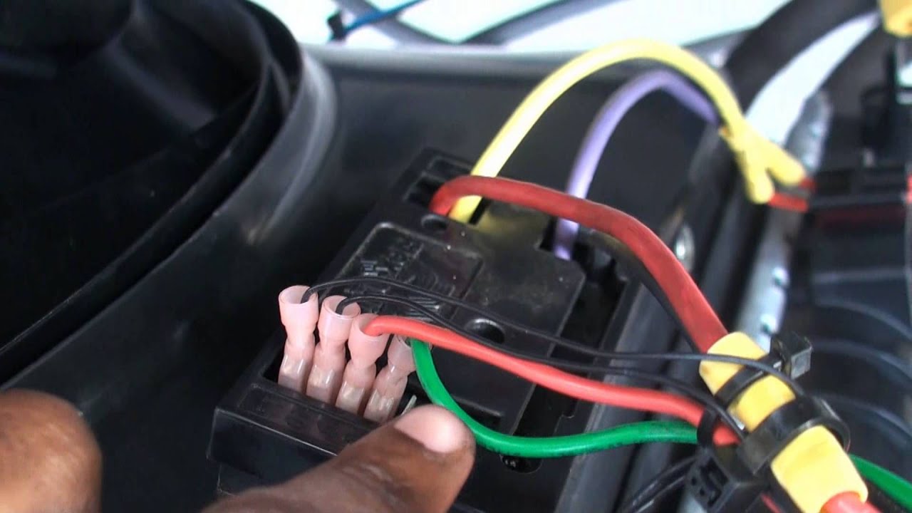
How To Wire Electric Cooling Fans with Crimp Connections
PDF 110&120 210&220 - Flex-a-Lite Step 8: (Optional) For manual switch operation, use Flex-a-lite p/n 31148. Connect the switch as shown on the wiring diagram (previous page). Connect the "M" terminal on the control module to the "1" terminal on the switch. Connect the "2" terminal on the switch to a positive 12v power source.
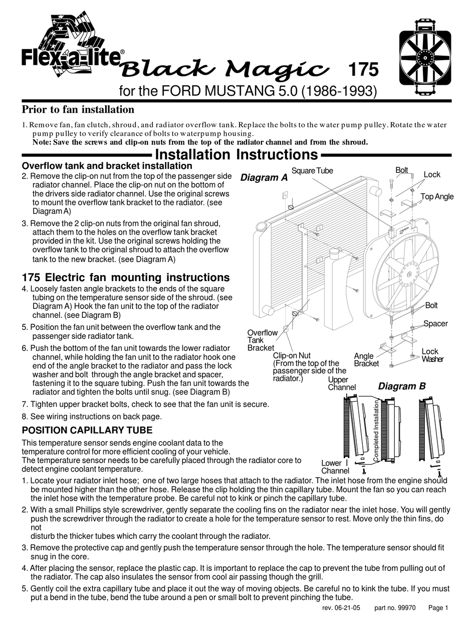
FLEX-A-LITE BLACK MAGIC 175 INSTALLATION INSTRUCTIONS Pdf ...
PDF #180 with controls #188 without controls - Flex-a-Lite trigger wire. Use the 3-way connector (included) to tap into this wire and send a signal to the fan control module. The fan will cycle on and off with the A/C clutch when the A/C is turned on. 6f. (Optional) For manual switch operation, use Flex-a-lite p/n 31148. Connect the switch as shown on the wiring diagram (previous page).
Variable Speed Control-VSC Wiring Instructions
3 Speed Fan Wiring Diagram - easywiring 3 speed fan wiring diagram. Look for a switch with four wires the manufacturer s wiring diagram search online for the make and model of fan plus the words wiring diagram wire cutters wire strippers and wire nuts. Hayden flex a lite or perma cool brands can provide a 12 volt output when activated. 2 to 1 2 med.
Dodge Ram Flex A Lite 183 fan install
12v Spdt Relay Wiring Diagram - easywiring Hayden flex a lite or perma cool brands can provide a 12 volt output when activated. 12v spdt relay wiring diagram. Relays shown in these diagrams can provide options for useful features such as an ac override on and or manual override on. A wiring diagram is a simplified traditional pictorial depiction of an electrical circuit.
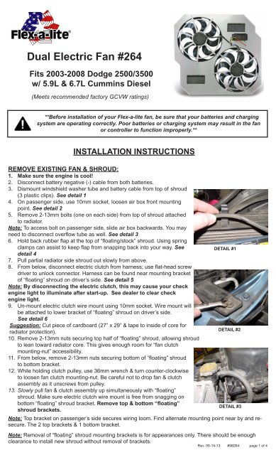
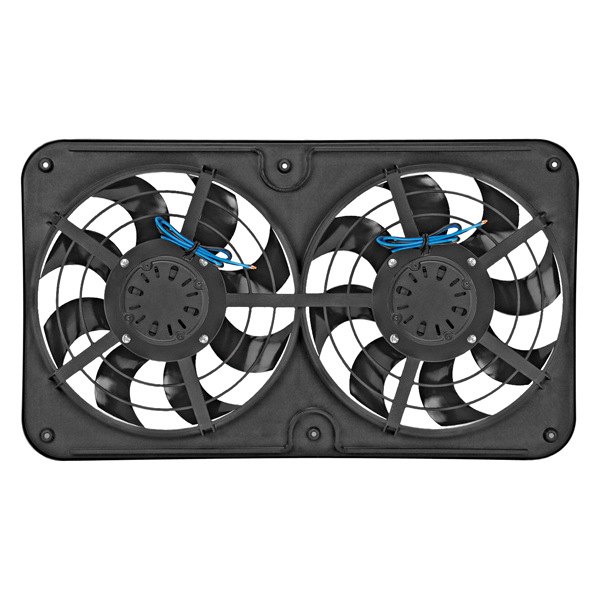
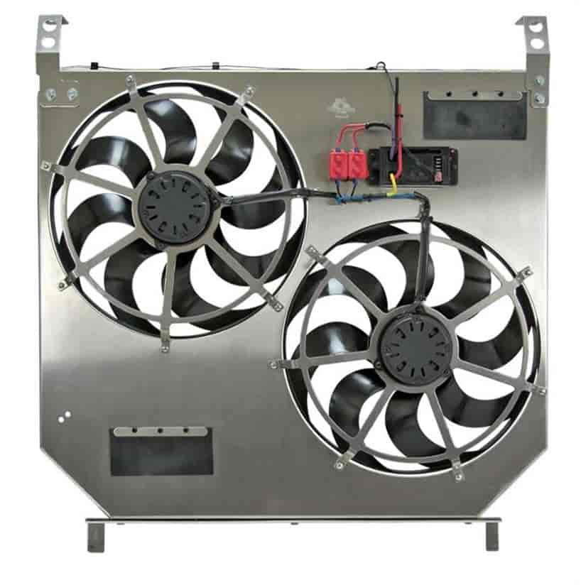
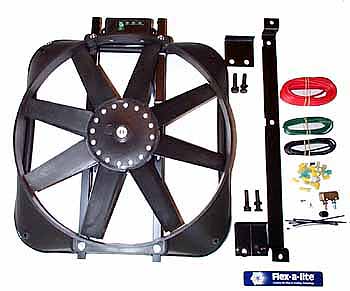
Dual Electric Fan #264 - Flex-a-lite Consolidated
saitami.serramenti.padova.itHarley chart size rear axle [M2ETK8] Feb 23, 2022 · Search: Harley rear axle size chart. I wasn't sure if ThunderMax® would live up to what I read and saw, but it is all that and much more In this version sold from year 2005 , the dry weight is 332 If you are unsure of the proper torque value to use, here is a general chart of fastener torque values 75" (10-19)*** I have a 2007 deluxe with a bum rear wheel 40”/15 40”/15.
Dual Electric Fan #264
Flex A Lite Electric Fan Controller Wiring Diagram ... Installation And Wiring Quick Start Motor Control Kit 31173 31174. Installation instructions troubleshoot issues with a flex lite variable sd control vsc wiring 106999 mark viii electric fan rear 180 manual override switch adjule temperature kit vintage air trinary w 150 99981 black magic fans cool down our 6 0l 106908 dual 264 part number 31149 temp module equip sels compact quick start motor ...
Flex-a-Lite® 490 - X-Treme S-Blade Electric Fan
PDF Flex-A-Lite Cooling Systems Installation Instructions WIRING DIAGRAM - MODEL 430 (PUSHER) 3A. Connect the fan wires to the VSC (Model 410 puller fan only) Now begin wiring the motors to the VSC. Using the large butt connectors provided, connect the red wire you attached to the fan motor wires in Step 2 to the yellow wire on the VSC. Connect the black wire from
Installation Instructions
Flex-A-Lite fan wiring install? | StangNet The other set of contacts is open when the fan is on. When the fan is off the set of contacts that were formally off are now on. Wire the indicator to that set of contacts. Wire sizes: Fan power feed & Fan ground 10 gauge stranded wire. Fan controls, relay & LED's 18 gauge stranded wire. Surge Dampner Diode: 1N4003

Vintage Air Trinary Switch w/ Flex-a-Lite Black Magic Fan ...
36 Series, Dual-Function, Flex-Lite, LED ... - Truck Lite 36203Y - 36 Series, Dual-Function, Flex-Lite, LED, Rectangular, Yellow, 3 Diode, Black, 12V
Flex-A-Lite Adjustable Electric Fan Controllers
PDF Installation Instructions - Flex-a-Lite For manual switch operation, use Flex-a-lite p/n 31148. Connect switch as shown on the wiring diagram (previous page). To override engine temperature and turn fan on, connect the switch to the "M" terminal on the control unit. NOTE: To prevent thermostatic activation (if only manual switch operation is desired),
Flex-A-Lite Pusher/Puller Straight Blade Fan 16" Fan Diameter
Flex A Lite Controller Wiring Diagram - Wiring Diagram Flex A Lite 106908 Adjule Electric Fan Controllers Summit Racing. Magic Show How To Install A Flex Lite Black Electric Fan Onallcylinders. Installation Instructions 180 With Controls 188 Without. Troubleshoot issues with a flex lite 31149 wiring diagram pdf installation instructions variable sd control vsc adjule temperature kit 31163 106999 ...

Flex-a-lite 398 Syclone Black 16" S-Blade Reversible Electric Fan
› document › 3913983082018 Full Book IET Wiring Regulations | PDF | Electrical ... 2018 Full Book IET Wiring Regulations - Free ebook download as PDF File (.pdf), Text File (.txt) or read book online for free. BS 7671-2018 IEC Wiring Regulations
Flex-a-Lite FLX-420 Electric Fan Kit - 2500 CFM Toyota Supra
PDF Adjustable Temperature Control Kit - Summit Racing Equipment (refer to wiring diagram below). Use the female connectors provided. 5. If manual control is desired, use Flex-a-lite P/N 31148. Refer to wiring diagram below. NOTE: If not using a Flex-a-lite manual switch, DO NOT connect the ground (-) wire to the switch! Insert the temp. sensor near the inlet hose... Then push the insulator cap over the end of the sensor.
Flex-A-Lite Direct-Fit Dual 15" Electric Fans 2003-07 Ford Super Duty 6.0L Diesel
› threads › 00-ram-1500-front00 Ram 1500, Front Driver Turn Signal Issues with 4x4 Light ... Feb 15, 2022 · I don’t have a wiring diagram handy, and I’m in the middle of a very heavy work week, but I’ll try to look when I have some time free. Just keep looking all over the sheet metal of the body, the frame, the battery ground terminal, the ground connections on the alternator, and the ground connections on the starter.

FLEX-A-LITE BLACK MAGIC 160 INSTALLATION INSTRUCTIONS Pdf ...
PDF 4-PIN COMPACT FLUORESCENT LAMPS INSTALLATION ... - Emergi-Lite 1.b) flex conduit wiring diagram: 2.a) flex conduit wiring diagram: inverter connector violet+ brown-white red a ballast ac lamp 1 lamp 2 c om n unswitched hot black 120v or orange 2 7v (c apunused lead) wall switch wht/blk blue blu/wht red yellow yel/blk blue red blue red white white yellow yellow black b b a emergency ballast b. two (2) lamp ...
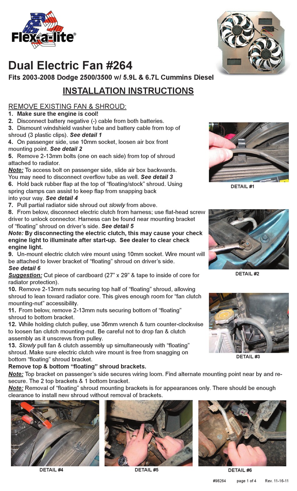
FLEX-A-LITE 264 INSTALLATION INSTRUCTIONS Pdf Download ...
PDF Part number 31149 Temp. Control Module - Flex-a-Lite Wiring Diagram 1a. Connect the motor wires to the control module (Red wire to the "M+" terminal and black wire to the "M-" terminal). 1b. Disconnect the negative battery lead for safety while finishing the wiring. Use the large diameter red (10 AWG) wire to run power directly from the battery positive (+) terminal to the "B" terminal on the control module.

11 Electrical ideas | automotive electrical, electricity, car ...

How to Install and Wire a Flex-A-Lite Electric Fan Controller
Wiring an electric fan. I am a novice with electrical | For B ...
Replaced engine fan with electric fan - Page 3 - DodgeForum.com

Flex-A-Lite Electric Fan
Dual Electric Fan #264
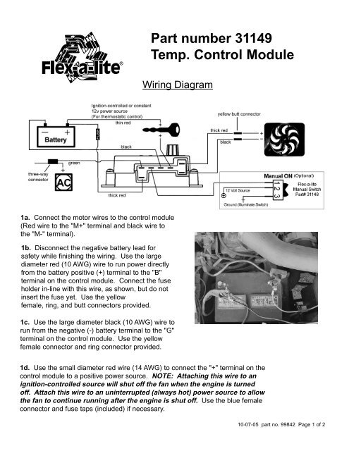
Part number 31149 Temp. Control Module - Flex-a-lite Consolidated
Flex-A-Lite Black Magic Xtreme Series Electric Fans
The Flex-a-lite illuminated 3-way switch allows for in ...
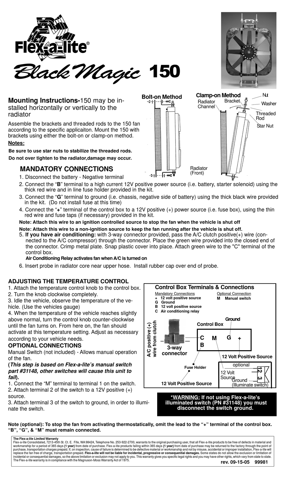
FLEX-A-LITE BLACK MAGIC 150 INSTALLATION INSTRUCTIONS Pdf ...
Untitled

30332 Flex-A-Lite Cooling Fan Control Module 30 Amp Rating
FORDMUSCLE.com web-magazine - Electric Fan Installation for ...
DIY: Low-Speed Cooling Fan Problem; a reasonably-priced ...

Flex-a-lite 31163 Variable Speed Control Module with Threaded Temperature Sensor,Black
Wiring Mark VIII electric fan with rear heater switch ...
Installation Instructions

Flex-a-lite Replacement Electric Fan Temperature Control Sending Units 33011K

Blog - How to Install Flex-a-lite's 3-Way Electric Fan Manual ...
Flex-A-Lite Cooling Systems Installation Instructions


Comments
Post a Comment