39 white rodgers gas valve wiring diagram
Installation - White Rodgers 36C03-300 Gas Valve ... White Rodgers 36C03-300 Gas Valve manual : Installation. ... All wiring should be installed in accordance with local and national electrical codes and ordinances. ... gas control. The typical wiring diagram shows only the terminal identification and wiring hook up. PDF 136840 36H GasValve SpecSheet - Emerson Electric Ignition Gas Valves 36H Series The versatile 36H Series gas valves cover a wide range of applications. Designed for use with most electronic ignition systems (HSI/DSI/Proven Pilot), it replaces hundreds of existing models in the field. The 36H Series is our highest capacity gas valve. White-Rodgers is the leading manufacturer of gas valves to ...
PDF White-Rodgers catalog R-4320 Wiring diagrams - see pages 171-174 Indicates Canadian Model Number SNAP OPEN, SINGLE FUNCTION, STANDING PILOT GAS VALVES 36C74-913 Step 24VAC Natural 3/ 4 x 3/ 4 Step 0.9"/3.5" 2.5"-5.0" No No No Str. Thru Yes Yes No 5 Open 136C94-303 24VAC / 2 x 3/ 4 Delay 3.5" 2.5"-5.0" Yes Yes No Str. Thru No Yes No 15

White rodgers gas valve wiring diagram
TH, TR, and TH/TR Gas Valve Terminals - HVAC School Let's look at what each of these terminals means: TH - The 24v hot leg from the thermostat on a call for heat (R+W closing) to the gas valve (TH terminal) to open the solenoid to allow gas to flow. This is assuming that the transformer is good and the high limit is closed. TR - The 24v common/return side of the transformer.; TH/TR - This is not internally wired to the gas valve. White Rodgers Gas Valve Wiring Diagram - Wirings Diagram As stated earlier, the lines at a White Rodgers Gas Valve Wiring Diagram signifies wires. Sometimes, the wires will cross. But, it does not mean connection between the cables. Injunction of 2 wires is usually indicated by black dot on the junction of 2 lines. PDF White Rodgers Furnace Controls - ontimemall.com 62 FURNACE 36E GAS VALVES 36E REDUNDANT GAS VALVE Compact Multifunction Valves Designed to Meet the Requirements for use with All Types of Intermittent Ignition Systems (Cycle-Pilot, Proven Pilot, Direct Spark Ignition and Hot Surface Ignition) FEATURES • Poppet style manual valve (capable of withstanding high inlet ...
White rodgers gas valve wiring diagram. White Rodgers Aquastat Wiring Diagram | Manual E-Books ... White Rodgers Gas Valve Wiring Diagram | Wiring Diagram - White Rodgers Gas Valve Wiring Diagram Wiring Diagram consists of numerous comprehensive illustrations that show the connection of various items. It contains instructions and diagrams for different kinds of wiring strategies as well as other things like lights, windows, etc. installation instructions- - 36c68 series combination gas valve sure, and a two-position gas cock knob for manual gas shut off. ... WHITE-RODGERS DIVISION ... This typical wiring diagram shows only the termi-.4 pages White Rodgers Gas Valve Wiring Diagram : Valves - White ... White Rodgers Gas Valve Wiring Diagram : Valves - White Rodgers Gas Valve - 3 - Page 1 36c wiring information gas valves 3 terminal panel fig.. A heat pump thermostat will use the orange wire for the reversing valve in the condenser. View thermostat white rodgers 1311 installation instructions online or download in pfd format. How to Install & Wire the Fan & Limit Controls on Furnaces ... Above: Wiring diagram for the White Rodgers Fan Limit Control used at line voltage. [Click to enlarge any image] adapted from the White Rodgers 5D51 installation instructions cited here. Below: Wiring diagram for the White Rodgers Fan Limit Control used with low voltage equipment. Note that the jumper is remoed for use with low voltage ...
Gas Solenoid Valve Wiring Diagram - U Wiring Variety of white rodgers gas valve wiring diagram. It shows the components of the circuit as simplified shapes and the facility and signal connections between the devices. Definitions Solenoid valves are found in many applications and are commonly used in refrigeration and air conditioning systems. Wiring diagrams are made up of two points. WHITE-RODGERS - Engineered Air WHITE-RODGERS DIVISION ... position gas cock, pressure regulator, 100% shut-off ... The typical wiring diagram shows only the terminal iden-.6 pages White Rodgers 1311 102 Wiring Diagram Sample - Wiring ... Name: white rodgers 1311 102 wiring diagram - White Rodgers Gas Valve Wiring Diagram 36 03 Wiring Diagram; File Type: JPG; Source: littleforestgirl.net; Size: 848.03 KB; Dimension: 1624 x 2189 White Rodgers Gas Valve Wiring Diagram Collection - Wiring ... Please download these white rodgers gas valve wiring diagram by using the download button, or right click selected image, then use Save Image menu. Wiring diagrams help technicians to find out the way the controls are wired to the system. Many people can see and understand schematics referred to as label or line diagrams.
36E24-214 (37-6108A) - PartsGuy WHITE-RODGERS DIVISION. EMERSON ELECTRIC CO. 9797 REAVIS ROAD ... The 36E24-214 combination gas valve is designed for ... Gas valve wiring diagram.6 pages White Rodgers 50E47 843 Wiring Diagram | Schematic Diagram ... As stated earlier, the lines in a White Rodgers Gas Valve Wiring Diagram represents wires. Sometimes, the cables will cross. But, it does not mean connection between the wires. Injunction of two wires is usually indicated by black dot on the junction of two lines. There'll be primary lines that are represented by L1, L2, L3, and so on. White Rodgers Fan Control Wiring Diagrams - Wire White rodgers gas valve wiring diagram collections of gas solenoid valve wiring diagram new fine white rodgers gas valve. White rodgers fan control wiring diagrams. Any attempt to re calibrate this control will void the white rodgers warranty. If in doubt about whether your wiring is millivolt. It shows the parts of the circuit as simplified ... White Rodgers 3 Wire Zone Valve Wiring Diagram - alejandrarori White rodgers 1311 102 hydronic zone page 3 of thermostat emerson 103 user manual manualzz wire valve wiring diagram diagrams control a with 2 aquastat gas to detect 24vac has closed three 4 taco esp way rogers 1e35 910 system nest 3rd gen thermostats circulator relay 1361 installation instructions ecobee. 4 wire thermostat wiring color code ...
Air Pressure Switch in Gas Water Heater Malfunctions ...
PDF 36c Wiring Information Gas Valves 36C87 GAS VALVE C L Main Valve Relay Coil Pilot Solenoid Coil Pressure Switch (N .O .) 3098 MERCURY FLAME SENSOR Hot Cold Common Plug-In 2 3 4 Fig.11 36C WIRING INFORMATION GAS VALVES 174 TECHNICAL HELP

XUD11ATE/Y ENGINE - WIRING DIAGRAMS
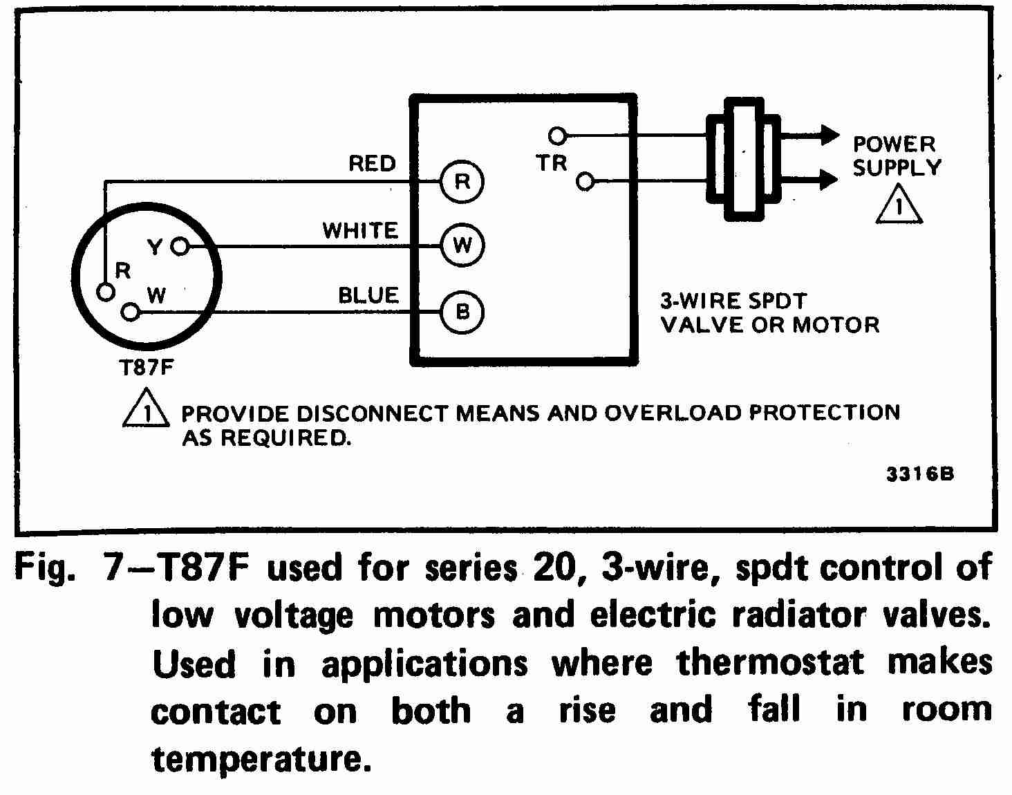
White Rodgers Zone Valve Wiring Diagram The old t'stat had red-to-red, white-to-white and the green wire attached to the Y terminal on a Honeywell series 20 t'stat. White Rodgers Zone Valve Wiring Diagram - If you have a White-Rodgers heat pump and thermostat system, or an Emerson thermostat, the wiring likely follows a particular pattern.

Upgrading White-Rodgers thermostat- wiring pictures ...
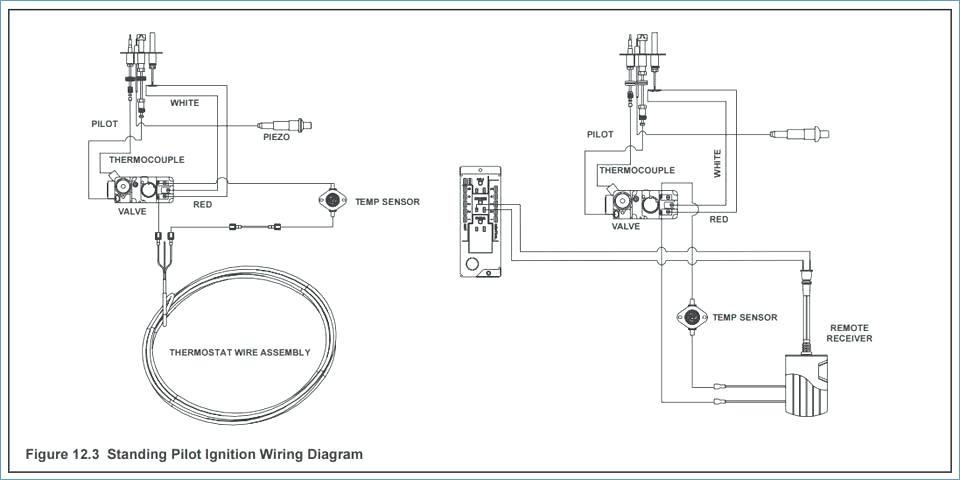
PDF Combination Gas Valve by INSTALLATION INSTRUCTIONS DESCRIPTION Combination Gas Valve . by . White-Rodgers Model E . INSTALLATION INSTRUCTIONS DESCRIPTION. The 857 Model E Midgitrol® Combination Gas Valve . Regulator. adjustment. provides all manual and automatic gas control functions required for gas-fired heating systems. 857 valves are intended for use with a continuous ignition source.

White Rodgers Zone Valve Wiring Diagram
White Rodgers F19-0097 Wiring Diagram - schematron.org White Rodgers F19-0097 Wiring Diagram 16.10.2018 4 Comments INSTALLATION INSTRUCTIONS. TYPE HYDRONIC ZONE VALVES. (3 WIRE). The schematic shows the valve in the closed position. As the thermostat. I also have white rogers mercury thermostats that control the zones (They F - White Rodgers F - 3 Wire Motor Assembly For.
Old Room thermostat wiring diagram links
PDF 36e Gas Burner Gas Valves Controls 62 FURNACE 36E GAS VALVES 36E REDUNDANT GAS VALVE Compact Multifunction Valves Designed to Meet the Requirements for use with All Types of Intermittent Ignition Systems (Cycle-Pilot, Proven Pilot, Direct Spark Ignition and Hot Surface Ignition) ... Wiring diagrams see page 254 ...

White Rodgers 1f78 Wiring Diagram
PDF Gas Valve Instruction Sheet - Emerson US WHITE-RODGERS DIVISION EMERSON ELECTRIC CO. 9797 REAVIS ROAD ST. LOUIS, MISSOURI 63123-5398 DESCRIPTION ... Gas valve wiring diagram M C P 1 2 3 Main Redundant M C P Redundant Solenoid Valve Main Solenoid Valve Horizontal Drop Piped Gas Supply 3 in. Gas Valve minimum Gas Valve Riser Piped Gas Supply
White Rodgers 24V AC Combination Gas Valve - Sears Marketplace
PDF 36g54 & 36g55 36j54 & 36j55 White-Rodgers is a division of Emerson Electric Co. ... Do not use a gas valve which appears to be damaged. A damaged valve may cause personal injury ... Fig. 3 - Four spade connector wiring diagram Piped Gas Supply Piped Gas Supply Tubing Gas Supply NOTE: ALWAYS INCLUDE A DRIP LEG IN PIPING NOTE: A MANUAL SHUTOFF VALVE
34 White Rodgers Gas Valve Wiring Diagram - Wiring Diagram ...
White Rodgers furnace gas valve wiring? | Terry Love ... (White Rodgers 36E24-204) is not wired according to the diagram. I replaced the controller with this Honeywell S8670K unit about 10-11 years ago and it has been working fine BUT I noticed today that the common on the gas control valve is connected to 24V-ground and not the designated MV/PV common port on the control unit.

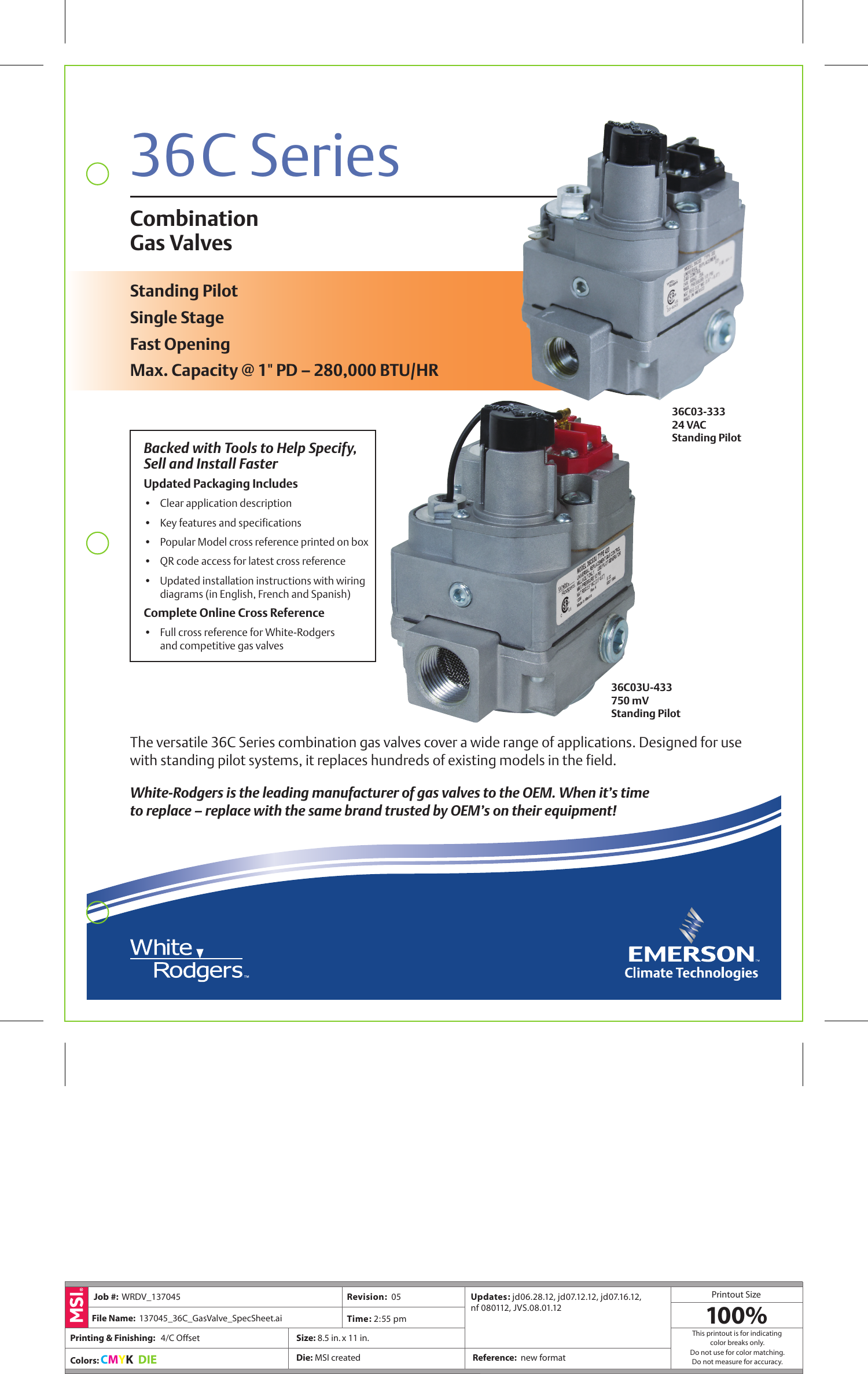
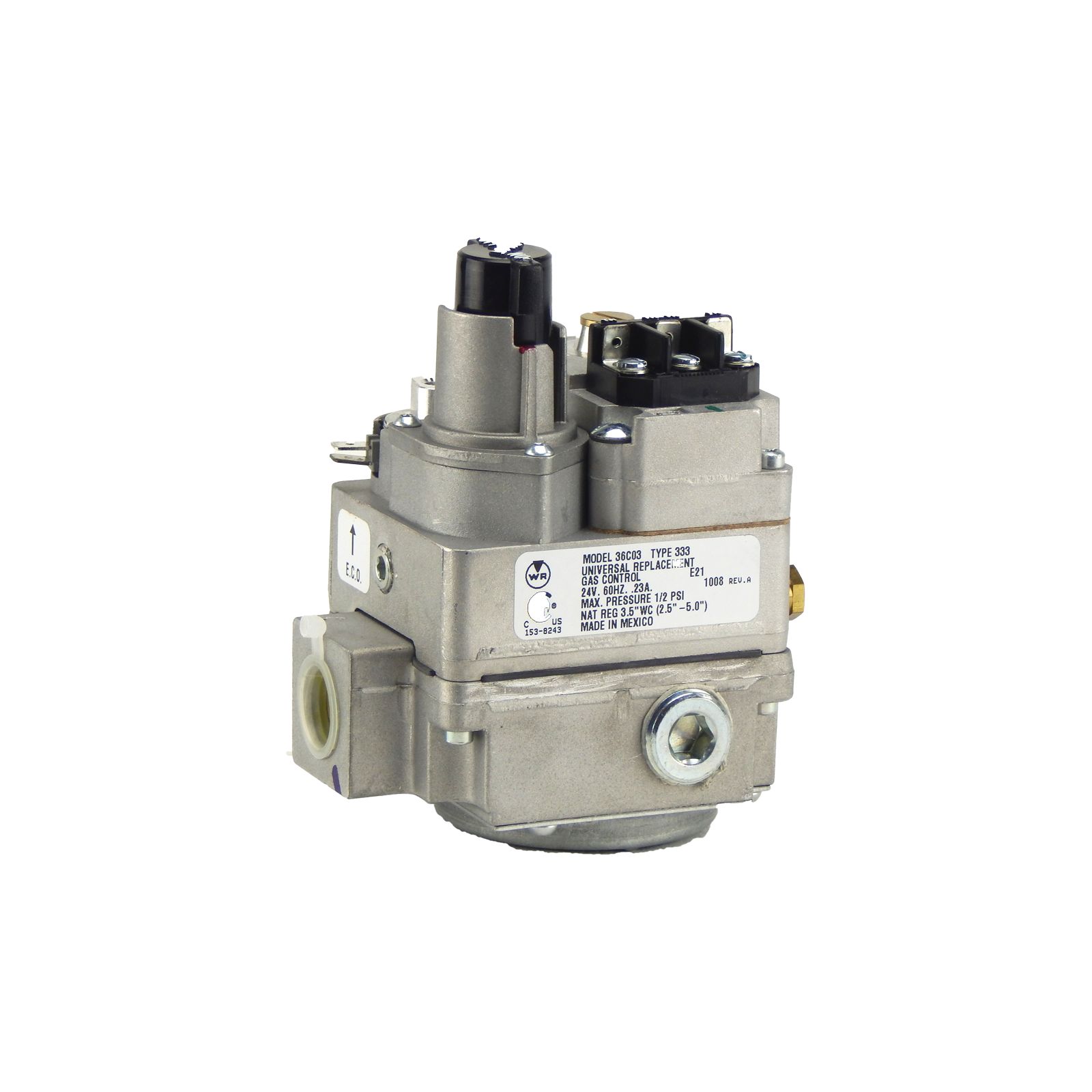
White-Rodgers 36C03-333 24V gas valve
White Rodgers Type 91 Relay Wiring Diagram - easywiring White rodgers gas valve wiring diagram new best white rodgers type 91 relay wiring diagram electrical outlet. White rodgers replacement heavy duty switching fan relay. It reveals the components of the circuit as streamlined shapes and the power and signal connections between the devices. View and download white rodgers 24a06g 1 installation ...
Updated & Corrected Zone Valve Wiring Schematic - YouTube
PDF TYPE 1311 - SupplyHouse.com WHITE-RODGERS DIVISION EMERSON ELECTRIC CO. 9797 REAVIS RD., ST. ... Alternate Wiring for using 750 Mv. Gas Valve Alternate Connections For Type 8A02A Relay Fig. 7 Diagram for Oil-fired System using 8A03A-2 24 VAC HIGH LIMIT GAS VALVE 1 3 MUST BE N.E.C. CLASS 1 WIRING Fig. 7a Diagram for Gas-Fired System All wiring should be done according to ...
Grundfos Submersible Pump Wiring Diagram Collection ...
PDF 36C WIRING INFORMATION - SupplyHouse.com 36C87 GAS VALVE C L Main Valve Relay Coil Pilot Solenoid Coil Pressure Switch (N.O.) 3098 MERCURY FLAME SENSOR Hot Cold Common Plug-In 2 3 4 Fig.11 36C WIRING INFORMATION TECHNICAL HELP 173
34 White Rodgers Gas Valve Wiring Diagram - Wiring Diagram ...
36c76 gas valve manual - Breizhbook Download >> Download 36c76 gas valve manual Read Online >> Read Online 36c76 gas valve manual white rodgers gas valve wiring diagram 36c67 gas valve white rodgers 36d24-901 wiring diagram 36c01a type 284white rodgers gas valve conversion kit 36c84 gas valve white rodgers 36e gas valve manual white rodgers 36h gas valve manual. YORK Model BHN Dual Fuel Heat Pumps are single package units with ...
White Rodgers Zone Valve Wiring Diagram
36c-36d-gas-valves-instructions-en-4400084.pdf - Emerson ... The 36C/36D series HSI, DSI proven pilot gas valves are ... ➀ Wiring diagrams – see pages 4 & 5. LP. Internal. Regulator ... White-Rodgers is a division.

31 White Rodgers Gas Valve Wiring Diagram - Wiring Diagram ...
Products - Automation Solutions | Emerson Browse Emerson Automation Solutions products. Emerson is where technology and engineering come together to create solutions for the benefit of our customers, driven without compromise for a world in action.
PEUGEOT 406 - ENGINE TYPE: RGX ( XU10J2CTE ) - BOSCH ...
Wiring Diagram For White Rodgers Zone Valve Wiring Diagrams Wiring Diagram For White Rodgers Zone Valve Zone valves control the flow of water to a specific zone in a hydronic heating system. The White Rogers Zone Valves are available in 2 or 3 Wire Models, and . We include wiring diagrams and installation instructions for most zone valve model and .

White Rodgers Gas Valve Wiring Diagram - Gas Control Valve ...
Fisher™ FIELDVUE™ DVC2000 Digital Valve Controller ... At its very basic functionality, the DVC2000 digital valve controller has a local user interface that will allow you to configure, calibrate, and tune the instrument Years of control experience has brought this product line to a high level of reliability and dependability.
White Rodgers Zone Valve Wiring Diagram
PDF 36g22, 36g23, 36g24 & 36g52 36j22, 36j23, 36j24 & 36j52 LP Gas (2,500 BTU/cu. ft.) White-Rodgers is a division of Emerson Electric Co. 36G 36J. 2! WARNING If you do not follow these instructions exactly, a fire or explosion may ... and/or national fuel gas codes. Figure 3. Gas valve wiring diagram Rectifier Bridge Electric


Comments
Post a Comment