43 wilson alternator wiring diagram
If you are able to look at a manufacturer's diagram of the alternator's connectors, the wire that slides over Pin 1 of the alternator leads to the positive (+) connection on the vehicle's battery and senses voltage. If the voltage rises above or falls below 12 Volts, the alternator's internal voltage increases or reduces power output to ... Diagram For Walker - Great Installation Of Wiring Diagram • - Wilson Alternator Wiring Diagram. Wiring Diagram comes with several easy to stick to Wiring Diagram Guidelines. It's meant to aid all of the typical user in creating a proper system. These instructions will probably be easy to comprehend and use.
Common Delco SI Series Alternator Wiring Diagram. by David Smith Sep 22, 2016. We are commonly asked how to wire the Delco SI series alternators upon maintenance or upgrading from an older generator. While this series of unit often runs as a self exciting one wire, agricultural applications also used 3 wire connections to the alternator.

Wilson alternator wiring diagram
Aug 16, 2021 · Wilson Alternator Wiring Diagram wilson alternator wiring diagram Every electrical arrangement consists of various distinct components. Each part ought to be set and. Image Result For Fg Wilson Control Panel Wiring Diagram Electrical Circuit Diagram Electrical Diagram Electrical Wiring Diagram Wilson Alternator Wiring Diagram Alternator 90 15 6170 Wiring Diagram Home Wiring Diagram. Wilson ... Note For unit with 24 volt, 1 wire hookup use 90-01-3102 (40 Amp). Note For Niehoff use 90-07-1052 (80 Amp). Note For enclosed unit use 90-01-3078 (18 Amp). Note For Marine unit use 90-01-3103 (42 Amp). Note For unit with debris shield, fan and pulley use 90-01-4437. Note This 63A alternator is used to replace all lower Amp units. The 90-01 ... wilson alternator wiring diagram - You will need an extensive, skilled, and easy to comprehend Wiring Diagram. With this kind of an illustrative guide, you will have the ability to troubleshoot, avoid, and full your projects with ease. Not merely will it assist you to achieve your required results quicker, but additionally make the complete ...
Wilson alternator wiring diagram. The Part Search function searches against both Wilson and cross reference part numbers. There are three types of searches possible, depending on whether you know the exact part number needed or if you are trying to determine the correct one from incomplete information. Choose the desired type by clicking the round radio button next to the name. Mar 20, 2019 · Diagram For Walker – Great Installation Of Wiring Diagram • – Wilson Alternator Wiring Diagram. Wiring Diagram consists of numerous in depth illustrations that present the relationship of assorted things. It consists of directions and diagrams for different kinds of wiring techniques and other things like lights, windows, etc. How do I wire my marine alternator? Many alternators require ignition voltage to initiate charging. You must verify that all required connections are connected to the proper terminal and have the correct voltage in order for the alternator to operate properly. Below you will find the most common alternator circuits used on marine applications. This is a three-wire alternating wiring diagram showing the connections between the different components of a circuit. The circuit comprises three main wires: battery positive cable, voltage sensing wire, and ignition wire. The ignition input wire is attached to the engine.
Color Bar For Car Wiring Diagram - Great Installation Of Wiring - Wilson Alternator Wiring Diagram Wiring Diagram consists of several in depth illustrations that present the connection of various things. It consists of directions and diagrams for various kinds of wiring methods along with other items like lights, home windows, and so on. According to earlier, the traces in a Wilson Alternator Wiring Diagram signifies wires. At times, the cables will cross. However, it does not mean link between the cables. Injunction of two wires is generally indicated by black dot at the intersection of 2 lines. There will be primary lines which are represented by L1, L2, L3, and so on. How to wire alternator diagram. To wire a warning light remove the terminal plug cover and connect the 1 Left terminal looking from the back of the alternator to the warning light wire. It shows the components of the circuit as simplified shapes and the power and signal associates together with the devices. Step 6 Figure 1 Snap in the DA plug ... Wilson Alternator Wiring Diagram, 21 exciter wire battery light key switch to battery as mentioned before we need the correct voltage at the alternator for it to operate properly. It shows the components of the circuit as simplified shapes, and the gift and signal links amongst the devices.
Wilson Alternator Wiring Diagram – wiring diagram is a simplified gratifying pictorial representation of an electrical circuit. It shows the components of the circuit as simplified shapes, and the gift and signal links amongst the devices. A wiring diagram usually gives opinion just about the relative slant and promise of devices and ... Universal Alternator Wiring Diagram Save Iskra Solutions Of 6 - Wilson Alternator Wiring Diagram Wiring Diagram comes with several easy to follow Wiring Diagram Directions. It really is intended to aid all the typical consumer in developing a suitable system. These directions will probably be easy to comprehend and use. Free wiring diagrams here http://www.bbbind.com/free_tsb.html Enter vehicle info. Year , make , model an engine . Under system click on engine ,then under subsystem click on charging system . Then click the search button , then on the blue link . This diagram show all connection's on the alternator . All wire's should have B+ voltage , testing with a volt meter . New Wilson alternators are designed for customers who demand the reliability and performance we have proven on our remanufactured offerings. Our alternators are manufactured using 100% new premium parts and are tested to meet or exceed OE standards. As like our remanufactured units, every new alternator is tested prior to leaving our facility.
OEX Alternator 12V 55A (Mitsubishi Style) MXA299
and connect the red wire to the output side of the alternator 10/32 stud, take the long wire and connect to the + side of the coil. If you are using a coil with external ballast resistor connect this wire to the battery side or key switch side of How To Wire Alternator 12-VOLT NEGATIVE GROUND 3 WIRE INSTRUCTIONS www.vintageautogarage.com

90-17-8068 - Alternator (Wilson) | Up to 60% off Dealer Prices | TractorJoe.com
Some shimming or modification to the alternator mount may be required to assure proper alignment. 6. Connect the output cable (see cable sizing recommendations below) ground, field wire, stator (tach) wire if needed and other necessary wiring. Connect alternator to Balmar regulator wiring harness as indicated in wiring diagram included on Page 12.

Vincent Motorcycle Electrics
2 Alternator Basic wiring diagram. 21 Exciter wire Battery light Key Switch To Battery As mentioned before we need the correct voltage at the alternator for it to operate properly. This voltage down the exciter wire to the alternator. Oct 24, · gahi's diagram is the correct way to wire a GM 10SI/12SI, and utilize all the benefits of that great ...
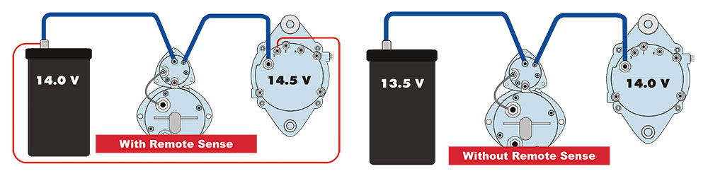
What are Remote Sense Alternators | Delco Remy
Gm 1 Wire Alternator Wiring Diagram Gm 1 Wire Alternator Wiring - Gm 4 Wire Alternator Wiring Diagram. You are able to often rely on Wiring Diagram as an essential reference that will help you save time and money. With the help of this e-book, you'll be able to effortlessly do your personal wiring tasks.

WILSON 90-01-3081
Technical Support . USA: 800.280.2737 Canada: 877.480.4034 M-F 7:00 - 7:00 CST More Details
ALTERNATORS - HEAVY DUTY DOMESTIC APPLICATIONS
4 Wire Alternator Wiring Diagram. Print the wiring diagram off plus use highlighters to trace the signal. When you make use of your finger or perhaps the actual circuit with your eyes, it is easy to mistrace the circuit. 1 trick that We 2 to printing a similar wiring plan off twice.

Delco 3 wire alternator wiring guide. Making a standalone 12v generator.
Wilson Alternator Wiring Diagram - Webtor - Wilson Alternator Wiring Diagram In addition, Wiring Diagram provides you with time frame in which the projects are to be finished. You will be able to understand exactly once the assignments ought to be completed, that makes it much simpler for you to correctly handle your time and effort.

Buy New DB Electrical AMN0003 Alternator Compatible With ...
29627 Renaissance Blvd. Daphne, AL 36526. Phone USA: 800.280.2737. Phone Canada: 877.480.4034. Supporting Hours: Mon. – Fri. 7:00 AM – 7:00 PM CST
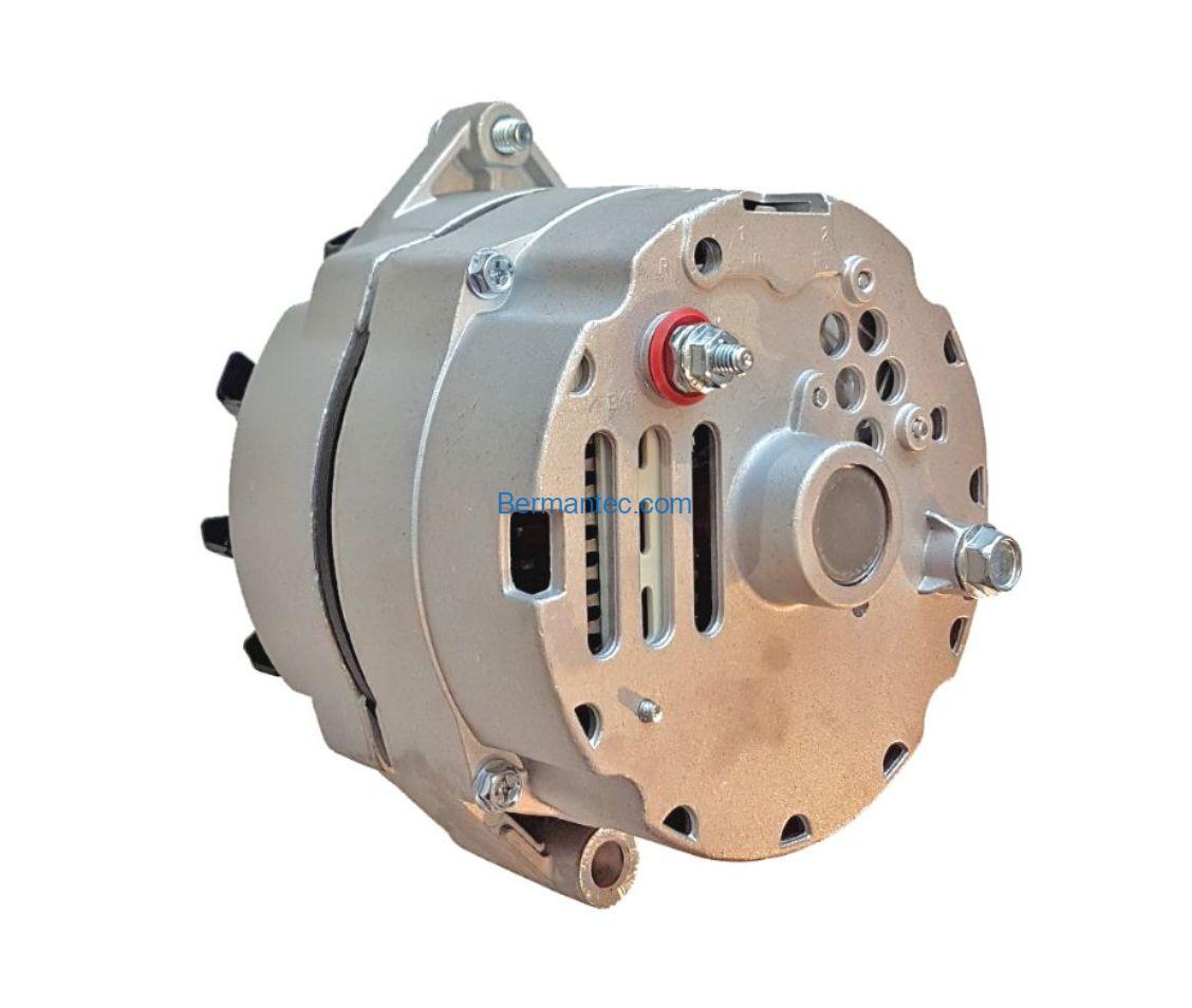
Alternator, 12V, 63A, 10SI. DA-02/63 | BermanTec
Jun 19, 2020 · Wilson Alternator Wiring Diagram from techteazer.com Print the wiring diagram off plus use highlighters to trace the signal. When you make use of your finger or perhaps the actual circuit with your eyes, it is easy to mistrace the circuit. 1 trick that We 2 to printing a similar wiring plan off twice.
Quality Built MPR7024111 - Rebuilt Alternator - Walmart.com
wilson alternator wiring diagram - You will need an extensive, skilled, and easy to comprehend Wiring Diagram. With this kind of an illustrative guide, you will have the ability to troubleshoot, avoid, and full your projects with ease. Not merely will it assist you to achieve your required results quicker, but additionally make the complete ...

Wilson - Part Details
Note For unit with 24 volt, 1 wire hookup use 90-01-3102 (40 Amp). Note For Niehoff use 90-07-1052 (80 Amp). Note For enclosed unit use 90-01-3078 (18 Amp). Note For Marine unit use 90-01-3103 (42 Amp). Note For unit with debris shield, fan and pulley use 90-01-4437. Note This 63A alternator is used to replace all lower Amp units. The 90-01 ...

50 Fresh Wilson Starter Wiring Diagram | Electrical circuit ...
Aug 16, 2021 · Wilson Alternator Wiring Diagram wilson alternator wiring diagram Every electrical arrangement consists of various distinct components. Each part ought to be set and. Image Result For Fg Wilson Control Panel Wiring Diagram Electrical Circuit Diagram Electrical Diagram Electrical Wiring Diagram Wilson Alternator Wiring Diagram Alternator 90 15 6170 Wiring Diagram Home Wiring Diagram. Wilson ...

China 12V 65A Alternator for Bosch Farm Lester 12146 ...
Wilson 65 Amp Alternator WIL90-15-6291 | O'Reilly Auto Parts
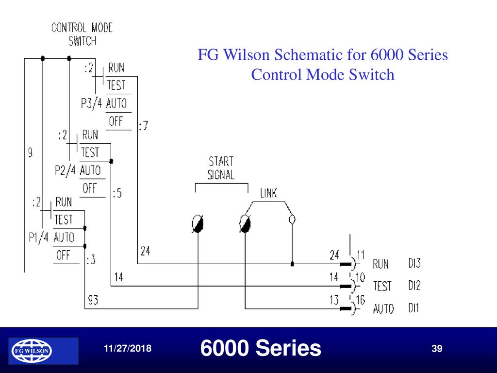
FG Wilson Product Training: 6000 Series Control System - ppt ...
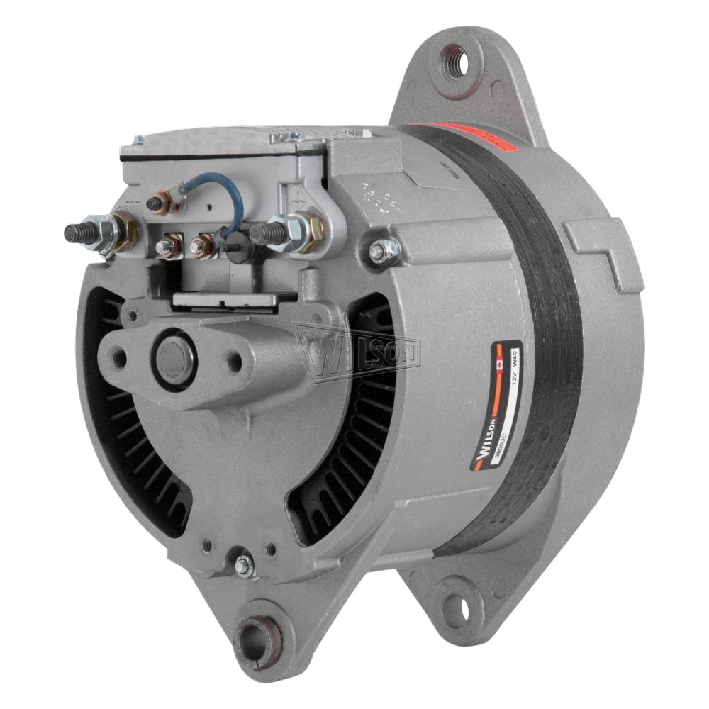
WILSON Automotive® - Remanufactured Alternator

Wilson - Part Details
What are the 2 wires on an alternator? - Quora

Alternator Wilson 90-05-9254 Reman | eBay

WILSON Automotive® - International 1652 1991 Alternator

90-22-5501 - Alternator (Wilson) | Up to 60% off Dealer Prices | TractorJoe.com

How to Wire a 1 Wire/3 Wire Alternator (10SI Delco Style) to a Farm Tractor
Proton Inspira APM Original Radiator Fan Motor for Proton Inspira, Mitsubishi Lancer CY4A T-GA-6702-GR17
Universal II AP Series

New DELCO Alternator for TRUCKS Applications; ADR0332, 400 ...

FGWilson Service

Ford Alternator #7078 - TUFF STUFF Performance Accessories
For 1999 Peterbilt 377 Alternator 88348DD 12.7L 6 Cyl Series ...

12V 120A Alternator for Bosch John Lester 12373 0120484027 ...

Car & Truck Charging & Starting Systems Car & Truck ...

12V DC Wiring Bible - Part 2 -Tech Article by BillaVista ...

How to Wire a GM External Regulated 10DN Alternator

DB Electrical Alternator For International Tractors 7088, 7288, 7388 1980-1986; 400-12324

康明斯66021491å‘电机859444å¡ç‰¹å½¼å‹’108026108275充电机,66021491 ...
2H Glow Plug Wilson Switch - Wiring Melting! | IH8MUD Forum

WILSON 90-05-9113

FG Wilson 10000-15115 10000-44894 Alternator Engine

90-04-7039 Alternator (New) Wilson

New DB Electrical Alternator Compatible BBB 7127-1W, BBB HD 7127-1W, N7127-1W, NAPA Power Premium Plus 213-4011SW, 7127-SEN-1, ADR0152
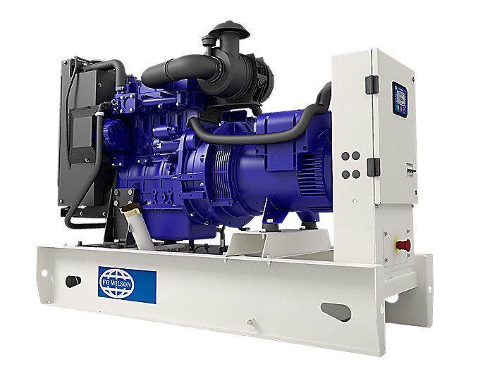
P22-6 | 20 kVA to 25 kVA Diesel Generator | Perkins Engine ...

Wilson - Part Details

Wilson - Part Details

10421 Alternator 12v 170a IR/EF 36SI Delco aftermarket


Comments
Post a Comment