42 system overview diagram
College Registration System Data flow diagram is often used as a preliminary step to create an overview of the College without going into great detail, which can later be elaborated.it normally consists of overall application dataflow and processes of the College process. System Dynamics is the study of the behavior of complex systems - seeking to understand the web of relationships between activities and to identify the linkage between cause and effect.System Diagrams are models used to visually express the dynamic forces acting upon the components of a process and the interactions between those forces.. System Diagrams are more than process flow charts.
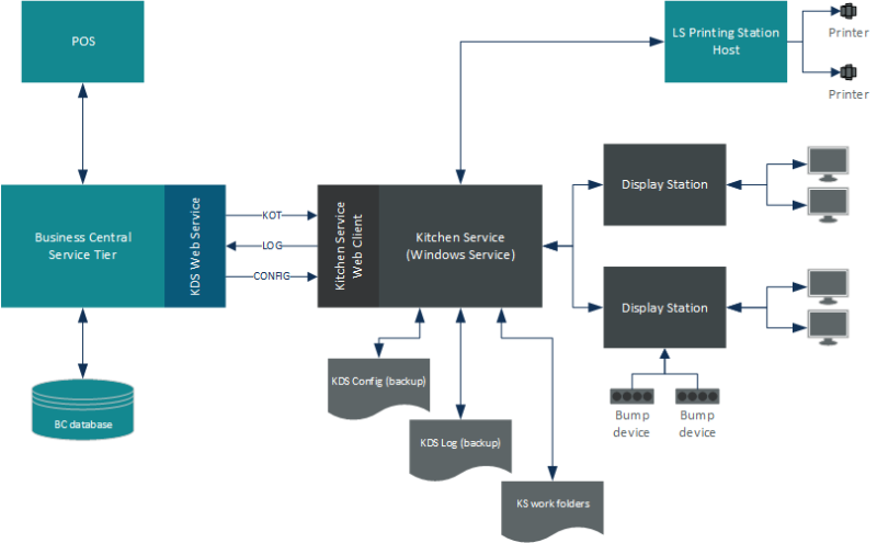
Architecture overview Diagram ( Block Diagram) Use Creately's easy online diagram editor to edit this diagram, collaborate with others and export results to multiple image formats. We were unable to load the diagram. You can edit this template on Creately's Visual Workspace to get started quickly. Adapt it to suit your needs by changing text ...
System overview diagram
An architecture diagram is a diagram that depicts a system that people use to abstract the software system's overall outline and build constraints, relations, and boundaries between components. It provides a complete view of the physical deployment of the evolution roadmap of the software system. Part 2: The Functions of an Architecture Diagram This type of UML diagram should be a high-level overview of the relationships between actors and systems, so it can be a great tool for explaining your system to a non-technical audience. UML Use Case Diagram for Online Shopping (Click on image to modify online) Visualize Your System - Overview of Diagrams in Manufacturing July 14, 2015 by Christoph Roser Organizing your manufacturing system is one of the keys to success in manufacturing. There are different tools available, although I have the feeling they are often mashed together or confused.
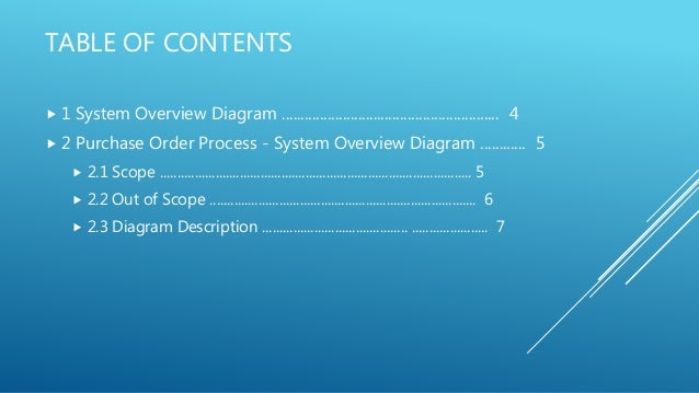
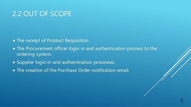
System overview diagram. FIGURE 1 - SYSTEM OVERVIEW DIAGRAM 4 5. 2.1 SCOPE The diagram (Figure 1) includes the activities and the systems involved in a purchase order raising process. The process begins with the Coles Procurement Officer who raises a purchase order once a Purchase Requisition (PR) is raised by the Coles Supermarket store person. System diagrams are particularly helpful in showing you how a change in one factor may impact elsewhere. They are excellent tools for flushing out the long term impacts of a change. Importantly, a good system diagram will show how changing a factor may feed back to affect itself! Drawing a system diagram is a good way of starting to build a ... NGSLR System Overview Introduction Document Number: Page | 4 NASA-NGSLR-Overview (v1.0) 1.2 Documentation Goals This document captures the configuration of the system during the collocation with MOBLAS-7 in the summer of 2013. It is intended to familiarize the reader with the NGSLR system and to serve as an aid in navigating the A system context diagram represents all external entities that may interact with a system. The entire software system is shown as a single process. Such a diagram pictures the system at the center, with no details of its interior structure, surrounded by all its External entities, interacting systems, and environments.
System Overview Diagram for Wordpress website? Ask Question Asked 5 years, 3 months ago. Active 1 year, 11 months ago. Viewed 3k times 1 I am trying to get my head around the system for a website using a Wordpress theme. I'm particularly confused at where Wordpress fits in, is it in the database, server or is it a standalone?? The use case diagram (behavior scenarios, precedents) is the initial conceptual representation of the system during its design and development. This diagram consists of actors, use cases and relationships between them. When constructing a diagram, common notation elements can also be used: notes and extension mechanisms. With the overview diagram, you can have an overview of your system, after all, you can study their relationships. Since the overview diagram is consist of thumbnail of diagrams that you have created previously, the overview of each diagram if find to be related to another diagram can be linked up with connectors. Creating an overview diagram Interaction overview diagrams show the dependencies and flow between various interaction diagrams, thus providing users with a higher-level overview of a system. Interaction occurrence Sometimes referred to as "interaction use". Used to refer to the contents of existing interaction diagrams. Can be identified as a box with "ref' in the corner.
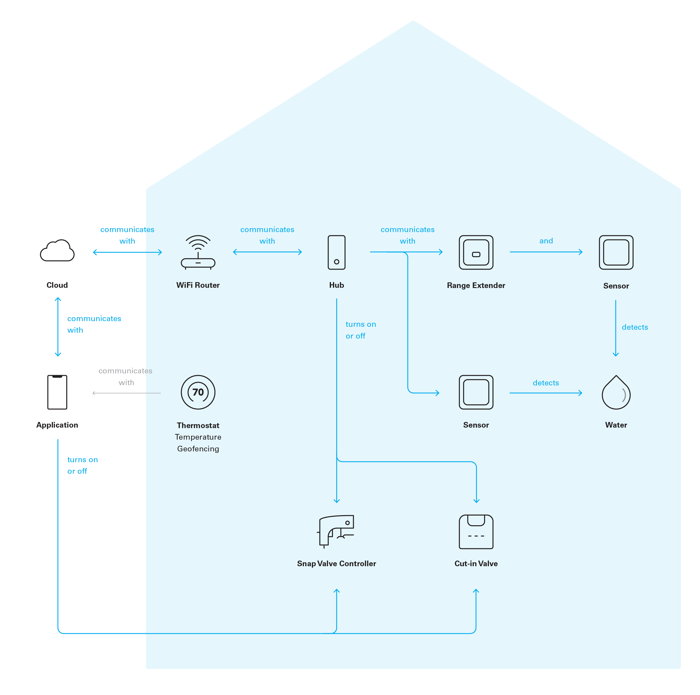
What is a system diagram? A system diagram is a visualization of a system as a flow-chart-like diagram. A system is marked by a box. The box marks the boundary of the system and completely contains it. The boundary need not be physically distinct. We place a label in the box identifying the system. Having decided on the agent types we now skip ahead to the developing the agent overview diagram from the system overview diagram. Figure 7 shows the overall design of the system. It depicts the... Credit Card Processing System UML Diagram. This sample shows the Use Case Diagram of the credit card processing system. You can see how the payment by credit card occurs. This sample can be used by the bank, financial enterprises, for understanding the work of the credit card processing system at the projecting the banking systems. Bank System The vector stencils … A system context diagram (SCD) in engineering is a diagram that defines the boundary between the system, or part of a system, and its environment, showing the entities that interact with it. This diagram is a high level view of a system. It is similar to a block diagram. Overview. System context diagrams show a system, as a whole and its inputs and outputs from/to …
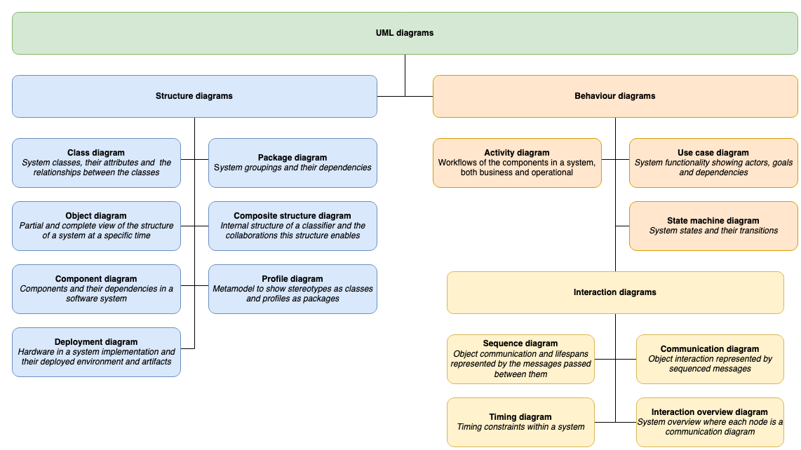
UML Diagram Types | Learn About All 14 Types of UML Diagrams
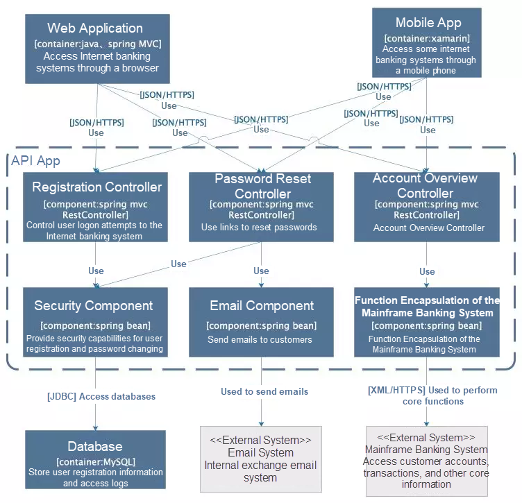
An application architecture diagram comprises a high-level overview of the components and fundamental interactions within the system, e.g. microservices, databases, etc. The application...
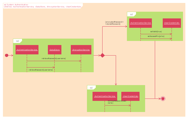
UML interaction overview diagram - System authentication ...
Charging System Overview & Conversion. Diagram #1 shows the basics of the early alternator / voltage regulator design. There are 2 brushes in the alternator, each one has a field terminal, one is labeled "FLD", the other is labeled "GND". The GND brush is grounded with the brush mounting screw. The other brush is the (+) brush (or field ...
Chapter 1 THE PROMETHEUS METHODOLOGY∗
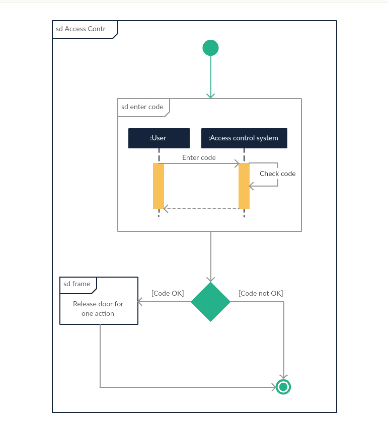
2. Interaction Overview Diagram Provides an overview in which the nodes represent communication diagrams. They are activity diagrams in which every node, instead of being an activity, is a rectangular frame containing an interaction diagram (i.e., a communication, interaction overview, sequence, or UML timing diagram).
System Overview | National Time & Signal
School Management System Data flow diagram is often used as a preliminary step to create an overview of the School without going into great detail, which can later be elaborated.it normally consists of overall application data flow and processes of the School process.

System Overview Diagram - EUDP
A basic human skeleton is studied in schools with a simple diagram. It is also studied in art schools, while in-depth study of the skeleton is done in the medical field. This article explains the bone structure of the human body, using a labeled skeletal system diagram and a simple technique to memorize the names of all the bones.

File:Qi wireless power interface specification - basic system ...
10.01.2014 · View Original Image at Full Size. Labeled diagram of the lungs/respiratory system. Image 37789 is a 1125 by 1408 pixel PNG Uploaded: …

Confluence Mobile - IU Libraries Confluence
Download scientific diagram | System Overview Diagram from publication: Towards an integrative methodology for developing multi-agent systems | A great number of methodologies to develop MAS ...

Interaction overview diagram - Wikipedia
Use deployment architecture diagrams to facilitate planning as you determine how many components are in the system, where they fit in the system, and how they communicate with each other. Typically, deployment diagrams are used to get an overview of the physical layout of the hardware and software in the system.
Interaction Diagrams for Example ATM System
Added the ability to define a hierarchy and decompose a software system into components and sub-components. The original UML specified nine diagrams; UML 2.x brings that number up to 13. The four new diagrams are called: communication diagram, composite structure diagram, interaction overview diagram, and timing diagram.
Blog - UML 2.5 shape library with updated shapes
system overview ( Concept Diagram) Use Creately's easy online diagram editor to edit this diagram, collaborate with others and export results to multiple image formats. We were unable to load the diagram. You can edit this template and create your own diagram.

Digital Video Surveillance System - Project
1 System Overview. Oracle Clinical is a database application that streamlines clinical trial management. It provides tools to manage all of clinical trial activities from your organizational infrastructure to preparing your results for submission. The foundation of the application is a flexible data model with the following features:
VTRAKH450 UHF-FM VehicleTracking Unit Block Diagram VTU s and ...
Elements of a System. The following diagram shows the elements of a system −. Outputs and Inputs. The main aim of a system is to produce an output which is useful for its user. Inputs are the information that enters into the system for processing. Output is the outcome of processing. Processor(s)

What is Interaction Overview Diagram?
Data Flow diagram A Data Flow Diagram (DFD) is a graphical representation of the "flow" of data through an information system, modeling its process aspects. A DFD is often used as a preliminary step to create an overview of the system, which can later be elaborated. Deployment Diagram Deployment diagrams are used to visualize the topology of ...

System Overview | plgd
ADVERTISEMENTS: Read this article to learn about Business System. After reading this article you will learn about: 1. Meaning of Business System 2. Objectives of Business System 3. Types. Meaning of Business System: The system helps the business organisations to achieve their goals. A business system is a combination of policies, personnel, equipment and computer […]

System Overview — RhodeCode Enterprise 4.26.0 4.26.0 ...
Interaction overview diagrams focus on the overview of the flow of control where the nodes are interactions (sd) or interaction use (ref). The other notation elements for interaction overview diagrams are the same as for activity and sequence diagrams. These include initial, final, decision, merge, fork and join nodes.

Introducing Types of UML Diagrams | Lucidchart Blog
System Overview. The Application Under Test (AUT). The Eyes SDK, called in the test suite code to trigger screenshot capture and visual checking. An application Driver, such as Selenium or Appium that provides a way for the test suite to send events to the AUT. The Eyes SDK also uses the Driver to capture the AUT screenshots.

18 System-integration-diagrams ideas | diagram, system, class ...
Operating System - Overview. Advertisements. Previous Page. Next Page . An Operating System (OS) is an interface between a computer user and computer hardware. An operating system is a software which performs all the basic tasks like file management, memory management, process management, handling input and output, and controlling peripheral ...
System overview diagram
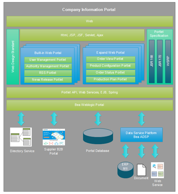
An Architecture Overview Diagram contains schematic diagrams that represent the governing ideas and building blocks of an IT system. An AOD can include both functional and operational concepts.

Sound System Overview — University Baptist Church
Visualize Your System - Overview of Diagrams in Manufacturing July 14, 2015 by Christoph Roser Organizing your manufacturing system is one of the keys to success in manufacturing. There are different tools available, although I have the feeling they are often mashed together or confused.

Introductory Guide to ConceptDraw's Rapid UML Solution
This type of UML diagram should be a high-level overview of the relationships between actors and systems, so it can be a great tool for explaining your system to a non-technical audience. UML Use Case Diagram for Online Shopping (Click on image to modify online)

A high level overview diagram of NewsStand's architecture ...
An architecture diagram is a diagram that depicts a system that people use to abstract the software system's overall outline and build constraints, relations, and boundaries between components. It provides a complete view of the physical deployment of the evolution roadmap of the software system. Part 2: The Functions of an Architecture Diagram
System overview diagram
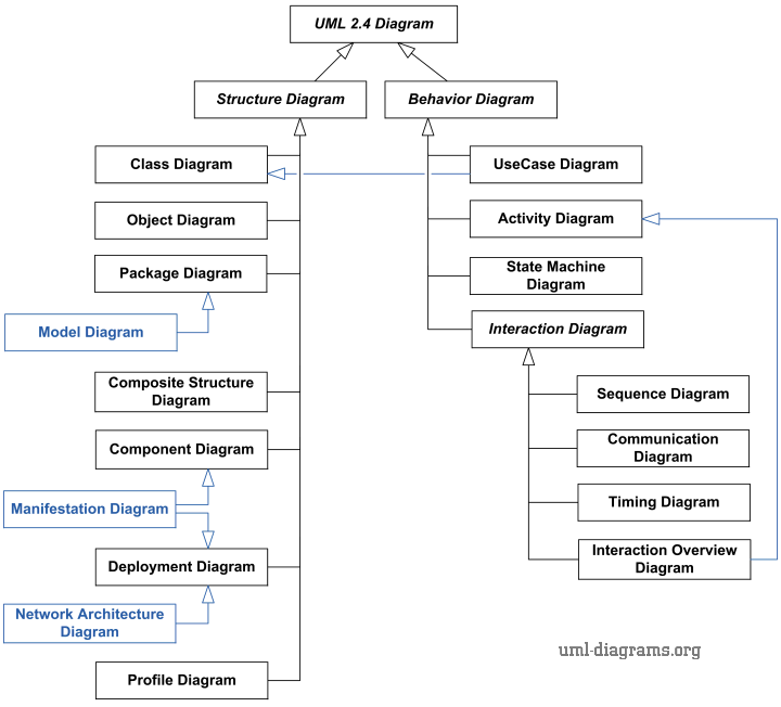
UML 2.4 Diagrams Overview
System Overview
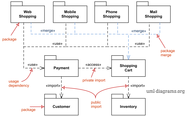
UML package diagrams overview - common types of package ...

Example System Overview Diagram | Download Scientific Diagram

SAP System Overview | SAP Training HQ

Interaction Overview Diagram UML2.0 | Professional UML Drawing

The C4 model for visualising software architecture
Draw the diagram of overview of an operating system ...
How to Create an Effective Technical Architectural Diagram ...

System Analysis and Design - Overview
Marina Menéndez-Pidal

System overview diagram | Download Scientific Diagram
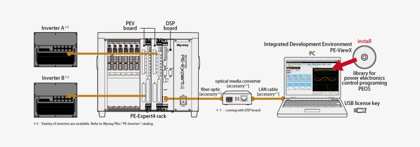
Pe-expert4 System Overview - Diagram Transparent PNG ...

Component overview and integration diagrams - Documentation ...
Template System - Diagram
The CRADIA system overview diagram. | Download Scientific Diagram

Example System Overview Diagram | Download Scientific Diagram

DEVELOPER PORTAL
Complete Guide to Architecture Diagrams - Edraw

Requirements specification via activity diagrams for agent ...


Comments
Post a Comment