41 electromagnet circuit diagram
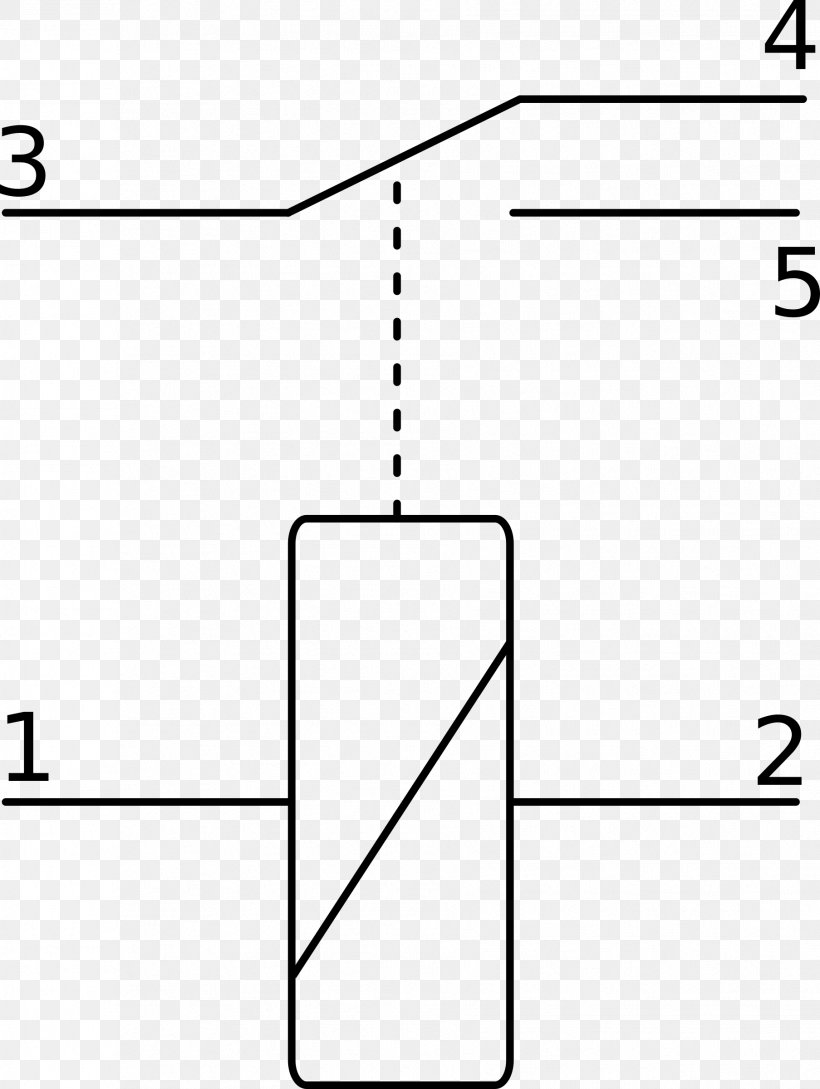
Looking at the diagram, we see the pinout of a typical 12V relay. Note that each pin is numbered. 85 and 86 are the coil pins while 30, 87, and 87a are the contact pins. 87 and 87a are the two contacts to which 30 will connect. If the coil is not activated, 30 will always be connected to 87a. The operation of this circuit is the same as the previous relay switching circuit. In this relay switch circuit, the relay load has been connected to the PNP transistors Collector. The ON-OFF switching action of the transistor and coil occurs when Vin is LOW, transistor “ON” and when Vin is HIGH, transistor “OFF”.
Short Circuit Test The SCC is a straight line since, for the short-circuited terminals, the magnitude of the armature current is 22 A A AS E I RX The equivalent generator’s circuit during SC The resulting phasor diagram

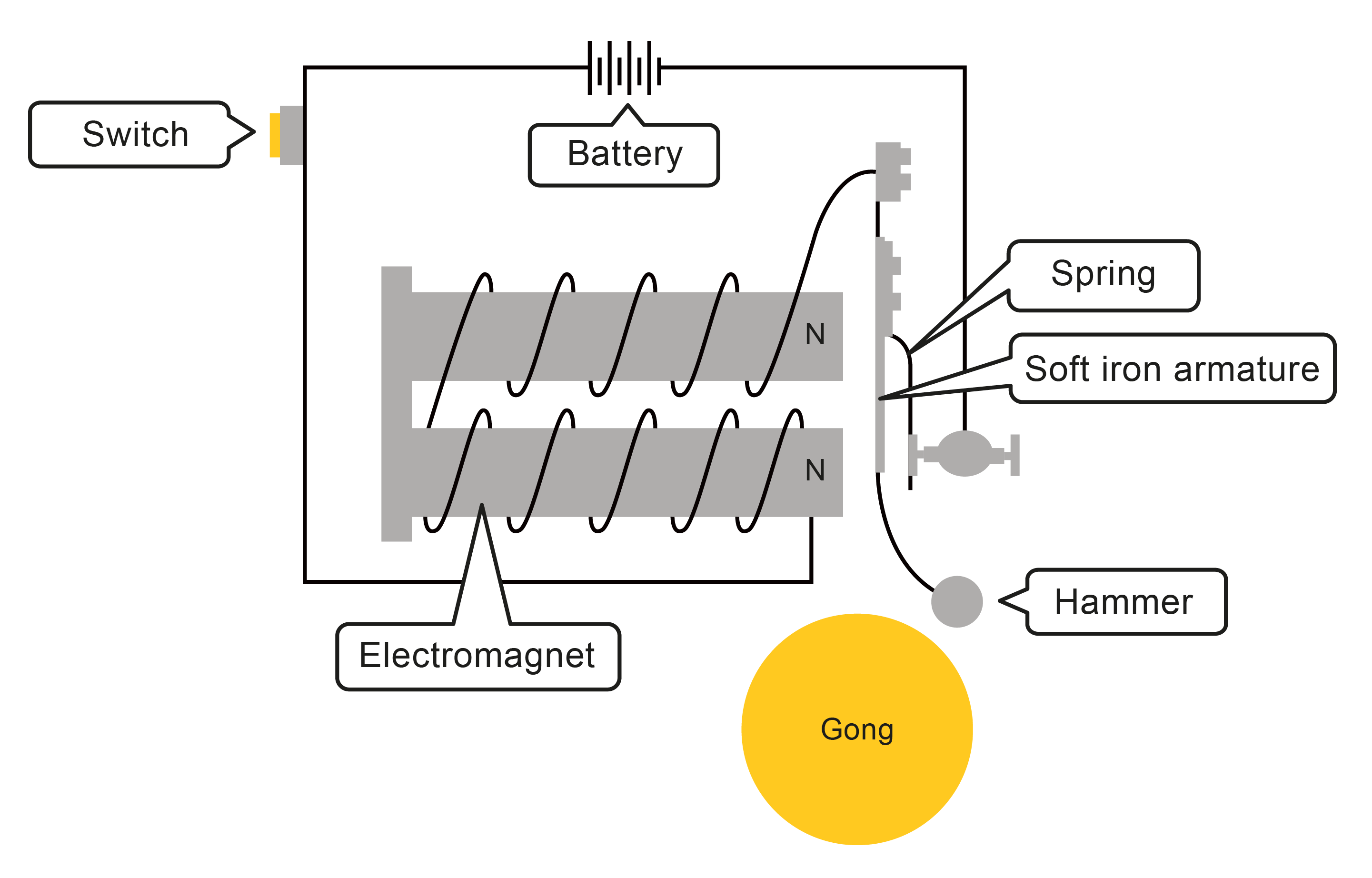
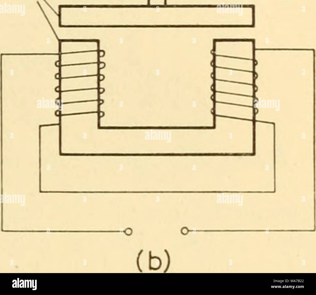
Electromagnet circuit diagram
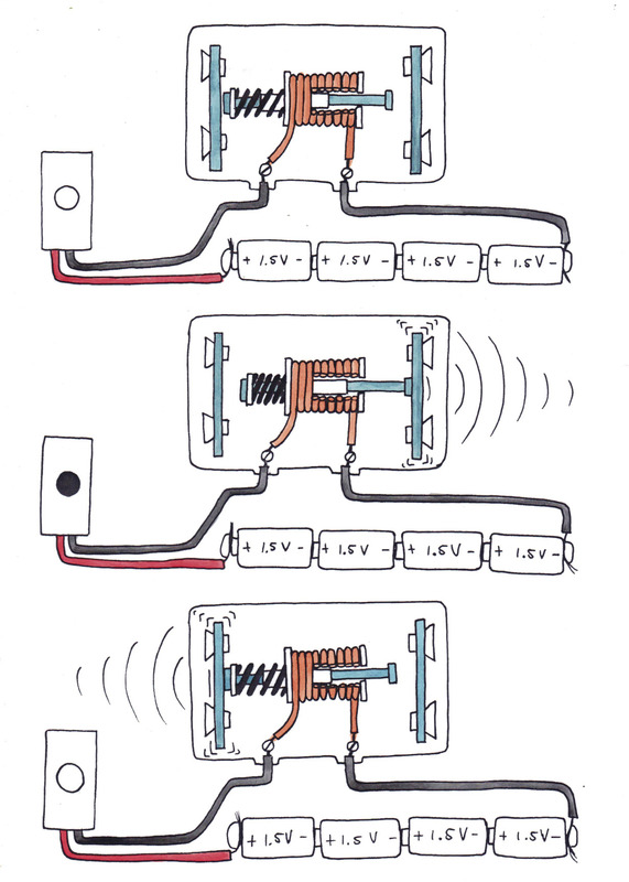
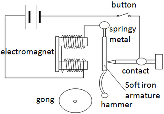
Apr 01, 2000 · The hardware of most traditional doorbells consists of a metal bell and metal clapper that, when the magnetic pull causes them to clang together, you hear the chime inside. The bell rings, the guest releases the button, the circuit opens and the doorbell stops its infernal ringing. This on-demand magnetism is what makes the electromagnet so useful. 3 Wire Alternator Wiring Diagram Source: www.carparts.com. This is a three-wire alternating wiring diagram showing the connections between the different components of a circuit. The circuit comprises three main wires: battery positive cable, voltage sensing wire, and ignition wire. The ignition input wire is attached to the engine. The construction of the negative sequence relay is shown in the figure below. The Z 1, Z 2, Z 3, and Z 4 are the four impedance of the circuit which is connected in the form of the bridge. The impedance is energized by the current transformers. The relay operating coil is connected to the midpoint of the circuit as shown in the figure below.
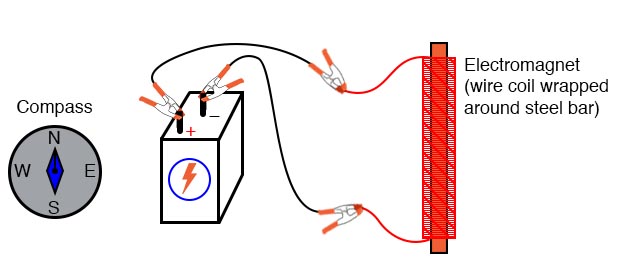
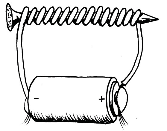
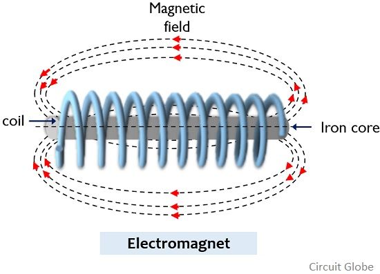
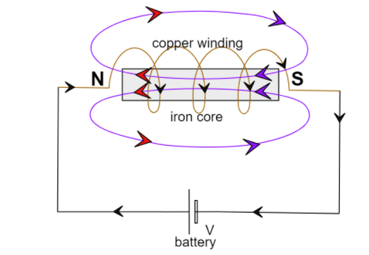
Electromagnet circuit diagram. Aug 06, 2021 · This electromagnet is activated by a simple power (+) and ground (-) much like a light bulb circuit. Terminals 87 and 30 are the secondary side of the relay which acts as the "switch" that connects electrical current from one terminal to the other. The construction of the negative sequence relay is shown in the figure below. The Z 1, Z 2, Z 3, and Z 4 are the four impedance of the circuit which is connected in the form of the bridge. The impedance is energized by the current transformers. The relay operating coil is connected to the midpoint of the circuit as shown in the figure below. 3 Wire Alternator Wiring Diagram Source: www.carparts.com. This is a three-wire alternating wiring diagram showing the connections between the different components of a circuit. The circuit comprises three main wires: battery positive cable, voltage sensing wire, and ignition wire. The ignition input wire is attached to the engine. Apr 01, 2000 · The hardware of most traditional doorbells consists of a metal bell and metal clapper that, when the magnetic pull causes them to clang together, you hear the chime inside. The bell rings, the guest releases the button, the circuit opens and the doorbell stops its infernal ringing. This on-demand magnetism is what makes the electromagnet so useful.
My portfolio: ELECTROMAGNET

what is an electromagnet? draw a circuit diagram to show how ...
Gr7 Technology
Electromagnets Worksheet - EdPlace

Electromagnet - Wikipedia
Electronic apparatus for biological research . Figure 33.23 ...

Electromagnetic Induction and Faradays Law
Electromagnets

Electromagnets - How electromagnets work | First4Magnets

OLCreate: TESSA_STP Module 3: Science – energy and movement ...
Application of Electromagnet - Excel@Physics

(a) Draw a circuit diagram to show how a soft iron piece can be transformed into an electromagnet

Electromagnet not functioning - Project Guidance - Arduino Forum
Electromagnetism Experiment | Basic Concepts and Test ...

(a) Draw a circuit diagram to show how a soft iron piece can be transformed into an electromagnet

Schematic diagram of a working electromagnetic terminal-wire ...

Electromagnet, Electromagnetic Coil and Permeability

a Draw a circuit diagram to show how a soft iron piece can be ...

Circuit diagram of the setup generating sine-wave ...
Basic Structure of the Circuitry of a Digital Computer
Gr7 Technology
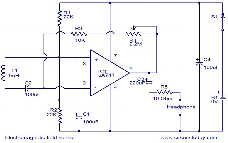
Electromagnetic field sensor circuit

Electromagnetic actuator circuit diagram. | Download ...

Circuit principle diagram of electromagnetic coupling ...
A Cyberphysics Page
Electronic Symbol Relay Wiring Diagram Electronic Circuit ...

Electromagnetic relay, diagram - Stock Image - C050/8194 ...
How Computers Work: Basics: Page 3

Uses of Electromagnet - Circuit Breaker | SPM Physics Form 4 ...

You Are Required to Make an Electromagnet from a Soft Iron ...
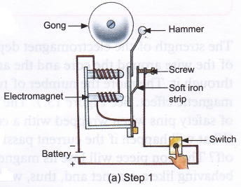
How does an electric bell work using electromagnets? - A Plus ...

Electromagnets in everyday use | IOPSpark
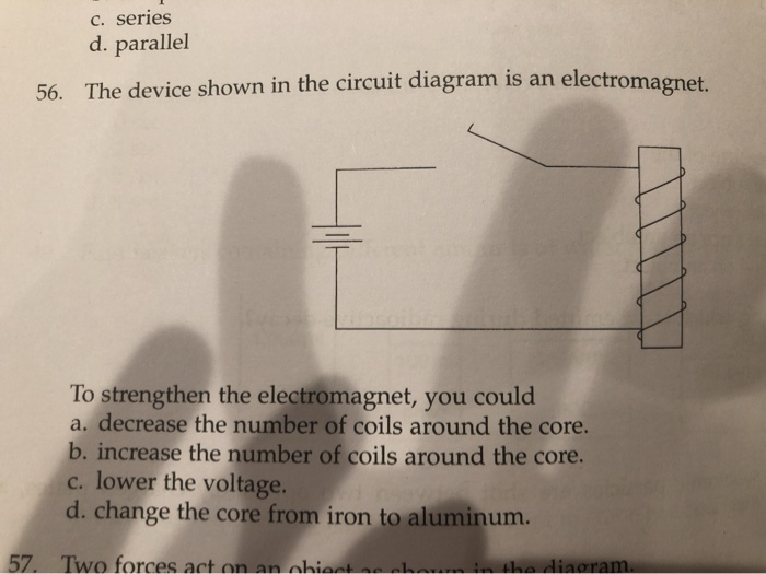
Solved C. series d. parallel 56. The device shown in the ...

Electromagnetic Induction and Faradays Law
Difference Between Electromagnet and Permanent Magnet (with ...

Tesla coil Electronic circuit Circuit diagram Wiring diagram ...

Electromagnetic Pendulum Help : r/AskElectronics
What is electromagnet Draw a circuit diagram to show class 12 ...

Power Supply Sees Electromagnet as a Short Circuit ...

6: Basic schematic diagram of the electromagnet driver ...

Lesson Worksheet:Magnetism and Electricity: Electromagnets ...


Comments
Post a Comment