39 Draw The Shear Diagram For The Beam.
Problem 7.55 Part A Draw The Shear Diagram For The… Answer to Problem 7.55 Part A Draw the shear diagram for the beam. Click on "add vertical line off to add discontinuity lines. The... (Solved) - Problem 7.70 Draw the shear diagram for the beam. Follow ... January 8, 2021 - 1 Answer to Problem 7.70 Draw the shear diagram for the beam. Follow the sign convention. (Figure 1) Click on "add vertical line off" to add discontinuity lines. Then click on "add segment" button to add functions between the lines add vertical line off delete + add segment â–¼ reset ? ...
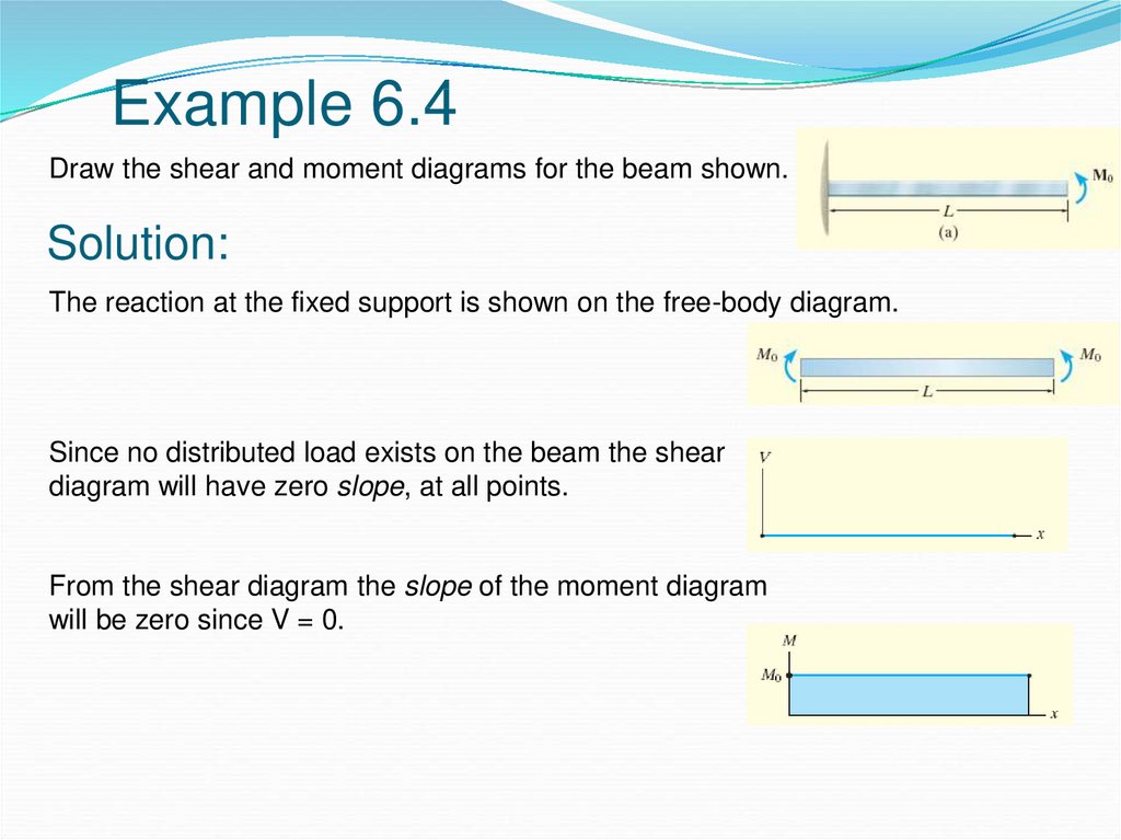
6.2 Shear/Moment Diagrams – Engineering Mechanics: Statics Shear Diagram. To create the shear force diagram, we will use the following process. Solve for all external forces acting on the body. Draw out a free body diagram of the body horizontally. Leave all distributed forces as distributed forces and do not replace them with the equivalent point load. Lined up below the free body diagram, draw a set of axes.

Draw the shear diagram for the beam.
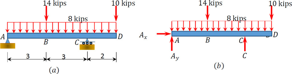
Answered: Draw the shear diagram of the beam… | bartleby ASK AN EXPERT. Engineering Civil Engineering Q&A Library Draw the shear diagram of the beam shown and determine the maximum shear. Incorrect diagram, no points. Show all necessary solutions. Draw the shear diagram of the beam shown and determine the maximum shear. Incorrect diagram, no points. Show all necessary solutions. Probn 4. For The Beam Shown In Figure 4, Draw The Shear ... Probn 4. For The Beam Shown In Figure 4, Draw The Shear Force Diagram And The Bending Moment Diagram. Label All Critical Values. 40 KN 60 KN/M A B60 120 KN K Am * 4m X 4m Figure 4. Beam Subjected To A Series Of Loads. How to draw shear force and Bending Moment Diagram of beam ... Using SW FEA 2D frame mobile application to draw shear force and Bending Moment Diagram of a beam structure.SW FEA is a finite element analysis app for the a...
Draw the shear diagram for the beam.. Drawing Shear Force Diagrams Effectively - MechanicalBase After finding all reaction forces on all supports, you can start the draw shear force diagram on that beam. Drawing Shear Force Diagram. In general, application, drawing shear force diagrams starts from left to right. The shear force diagram starts with the reaction of the left-most side of the beam, which can be simply supported or cantilevered. Take a look at the very basic simply supported example below. [Solved] For the beam and loading shown draw the shear and ... Are you looking for the beam and loading shown draw the shear and bending moment diagrams? then you are at the right place on the web. Beams come with different kinds and different types of loading on them. Hence, Submit your questio n and get solved within a few hours. Solved Draw the shear diagram for the beam. Draw the moment ... Draw the shear diagram for the beam. Draw the moment diagram for the beam. Who are the experts? Experts are tested by Chegg as specialists in their subject area. We review their content and use your feedback to keep the quality high. Transcribed image text: Draw the shear diagram for the beam. Draw the moment diagram for the beam. Shear Load and Bending Moment Diagrams Drawing shear force and bending ... (adding jumps at all point couples). The following is an example of one shear load and bending moment diagram. ... First draw the free-body-diagram of the beam with sufficient room under it for the shear and moment diagrams (if needed, ...
Solved: Problem 7.53 Part A Draw The Shear Diagram For The... | ... Answer to Problem 7.53 Part A Draw the shear diagram for the beam. Click on "add discontinuity" to add discontinuity lines. Then c... Shear Force and bending moment diagram for Simply ... Steps to draw Shear force and Bending moment diagrams In SFD and BMD diagrams Shear force or Bending moment represents the ordinates, and the Length of the beam represents the abscissa. Consider the left or the right portion of the section. Add the forces (including reactions) normal to the beam on the one of the portion. PDF Shear and Moment Diagrams - Memphis procedure for constructing the shear and moment diagrams for a beam. 2. To construct the shear diagram, first, establish the V and x axes and plot the value of the shear at each end of the beam. Shear and Moment Diagrams Procedure for analysis-the following is a procedure for constructing the shear and moment diagrams for a beam. PDF Chapter 4 Shear and Moment In Beams - ncyu.edu.tw It is visually desirable to draw the V-diagram below the FBD of the entire beam, and then draw the M-diagrambelow theV-diagram. The bending moment and shear force diagrams of the beam are composites of the Vand Mdiagrams of the segments. These diagrams are usually discontinuous, or have discontinuous slopes.
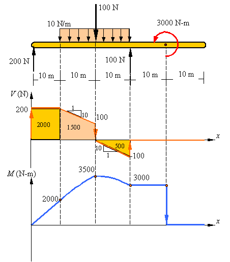
Shear Force and Bending Moment Diagram for Simply ... Shear Force and Bending Moment Diagram for a simply supported beam are as follows. Case 01. Simply supported beam with point load. Simply supported beam with point load. To find out Shear Force, first we will calculate R a and R c. Beam is simply supported ∑M a = ∑M c = 0. Let us consider ∑M a = 0. 6*4 - R c *8 = 0 (Clockwise bending ... Draw the shear diagram for the beam. follow the sign convention The shear force diagram for the beam is drawn using the calculated values as shown in Figure (6). The shear force diagram for the beam is, The shear force at each span is calculated using shear force equations (1), (2), and (3) from the Figure (5). Finally draw the shear force diagram using the obtained shear force values at each point. Step 3 of 3 Shear Force and bending moment diagram - ExtruDesign Steps to draw Shear force and Bending moment diagrams In SFD and BMD diagrams Shear force or Bending moment represents the ordinates, and the Length of the beam represents the abscissa. Consider the left or the right portion of the section. Add the forces (including reactions) normal to the beam on the one of the portion. Draw the shear diagram and the moment ... - HomeworkLib HomeworkLib.com is a free homework help website. You can ask any homework questions and get free help from tutors.
Bending moment and shear force diagram of a cantilever beam
Shear force and bending moment diagram - SlideShare Draw shear force and bending moment diagrams [SFD and BMD] for beam. Also determine maximum hogging bending moment. 30N/m 4m [Ans: Max. Hogging bending moment = 735 kNm] Exercise Problems 4m3m VM-79 80. 5kN 8. A cantilever beam of span 6m is subjected to three point loads at 1/3rd points as shown in the Fig. given below. Draw SFD and BMD for ...
Shear and moment diagram - Wikipedia
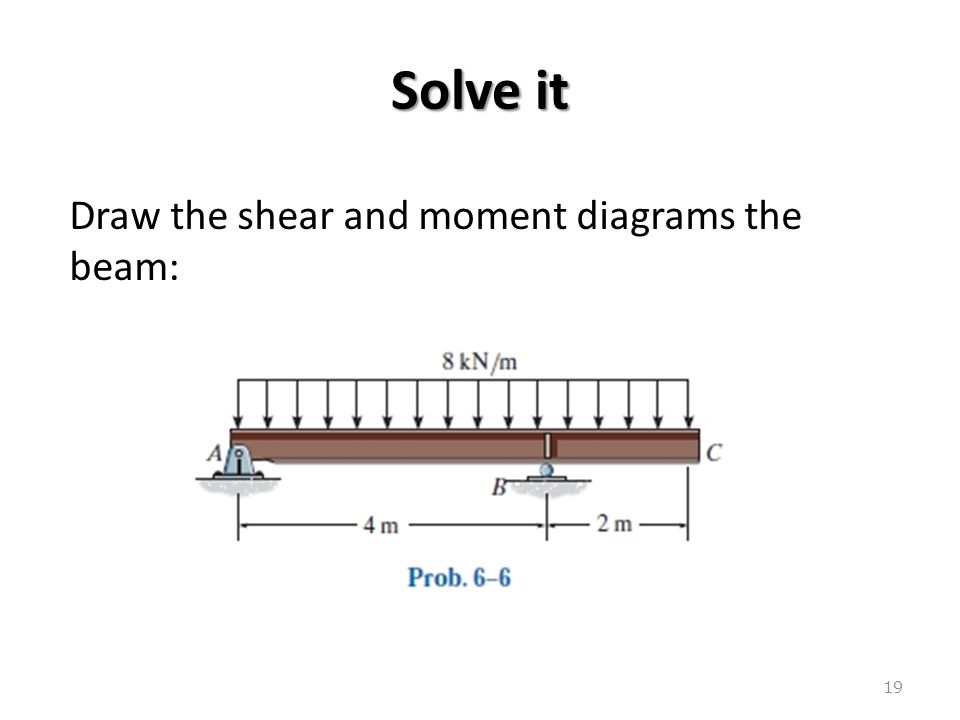
Draw The Shear And Moment Diagrams For The Overhang Beam. Answer to Draw the shear and Moment diagrams for the overhang beam. How the bending moment diagram of an overhanging beam will be if only we can draw the shear force diagram since it dictates the shape of bending moment . 6-5. Draw the shear and moment diagrams for the beam. 2 m. 3 m. 10 kN. 8 kN. 15 kNm. 6-6.
Draw the shear diagram for the beam. - StudentShare
Shear and moment diagram - Wikipedia The first drawing shows the beam with the applied forces and displacement constraints. The second drawing is the loading diagram with the reaction values given without the calculations shown or what most people call a free body diagram. The third drawing is the shear force diagram and the fourth ...
Chapter 4: Internal Forces in Beams and Frames” in ...
How to Draw Shear Diagrams | ReviewCivilPE April 13, 2012 - Shear diagrams are an easy way ... along a beam or member and also reveal the maximum positive and negative shear values. The first step will always be to simplify any and all load distributions into point loads and to solve for all exterior reactions. Begin the shear diagram by drawing a horizontal ...

2) (Group Solving Problem) Draw the shear force and bending ...
The Ultimate Guide to Shear and Moment Diagrams ... 4.0 Building Shear and Moment Diagrams. In the last section we worked out how to evaluate the internal shear force and bending moment at a discrete location using imaginary cuts. But to draw a shear force and bending moment diagram, we need to know how these values change across the structure.
Bending Shear and Moment Diagram, Graphical method to ...
Draw the shear and moment diagrams for the cantilevered beam Jan 04, 2022 · 6. Plot the shear force diagram (V versus x) and the bending moment diagram (M versus x). If V and M in the diagram are positive, their values are plotted above the x-axis, whereas negative values are plotted below the axis. 7. To enhance readability, show the shear force and moment diagrams below the free-body diagram of the beam. Sign convention:

Ultimate Guide to Shear Force and Bending Moment Diagrams ...
Draw the shear and moment diagrams for the beam shown in ... Draw the shear and moment diagrams for the beam shown in Fig. 6-6 a . | Holooly.com. Support Reactions. The distributed load is divided into triangular and rectangular component loadings and these loadings are then replaced by their resultant forces. The reactions have been determined as shown on the beam's free-body diagram, Fig. 6-6 b .

Draw the shear diagram and the moment diagram for the beam ...
Draw the shear-force and bending-moment diagram for the ... Draw the shear-force and bending-moment diagram for the beam shown in Fig. P7.32. Assume the upward reaction provided by the ground to be uniformly distributed. Label all significant points on each diagram. Determine the maximum value of (a) the internal shear force and (b) the internal bending moment.

Drawing Shear and Moment Diagrams for Beam - YouTube
7-55. Draw The Shear And Moment Diagrams For The Beam ... · Solved Draw The Shear Diagram For The Beam Follow The Si. 4.3 shear moment equations and shear moment diagrams the determination of the internal force system acting at a given section of a beam: draw a free body diagram that expose these forces and then compute the forces using equilibrium equations. the goal of the beam analysis -determine the shear force v and.
Draw the shear diagram for the beam. Draw the moment diagram ...
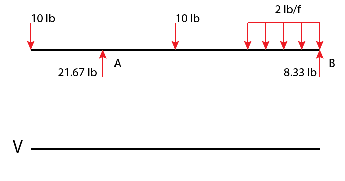
How to Draw Shear Diagrams | ReviewCivilPE The beam is 20ft long divided into 5 foot sections. Shear diagrams always begin and end at zero, with all of the forces on the member shown in between. Starting from the left, the first force you come across is the 10 lb downward force at the left end. This is the first point of data, draw a line from zero to negative 10.
How to draw shear force and bending moment diagrams (strength ...
How to Draw Shear Force & Bending Moment Diagram | Simply ... Draw shear force and bending moment diagram of simply supported beam carrying uniform distributed load and point loads. As shown in figure. Solution First find reactions R1 and R2 of simply supported beam. Reactions will be equal. Since, beam is symmetrical. R1 = R2 = W/2 = (600 +600 + 200 x4)/2 = 1000kg Hence, R1 = R2 = 1000 kg. Shear Force
Unit 6: Bending\. Shear and Moment Diagrams - online presentation
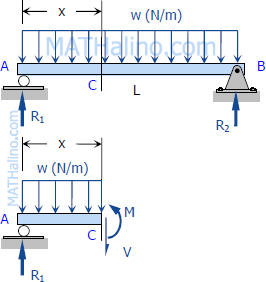
Shear and Moment Diagrams | Strength of Materials Review ... Shear and Moment Diagrams Shear and Moment Diagrams Consider a simple beam shown of length L that carries a uniform load of w (N/m) throughout its length and is held in equilibrium by reactions R 1 and R 2. Assume that the beam is cut at point C a distance of x from he left support and the portion of the beam to the right of C be removed.
Mechanics Map - Shear and Moment Diagrams
Free Online Beam Calculator | SkyCiv Engineering 5 days ago - Free online beam calculator that calculates the reactions, deflection and draws bending moment and shear force diagrams for cantilever or simply supported beams

Draw the shear diagram for the beam. Follow the sign ...
Calculating Shear Force Diagram | SkyCiv Engineering Dec 08, 2021 · So let’s consider the following example to calculate the shear force diagram of a beam: Source: SkyCiv Beam. Calculating Shear Force Diagram – Step 1: After you calculate the reactions at supports at A and B, start the Shear Force Diagram at the first value of the force acting on the beam. We take the sum of all vertical forces, which in this case, is just a +10kN due to the reaction at point A:
Solved) : Draw Shear Moment Diagrams Beam Also Determine ...
PDF Recitation #5 Understanding Shear Force and Bending Moment ... Therefore the bending moment diagram is: Example 2 Draw the shear force and bending moment diagrams for the beam show below: a) determine the reactions at the supports Taking moments about A (clockwise moments = anti-clockwise moments) (10 x 6) x 3 = 6RC where 10 x 6 =60kN = total load and 3m =distance from A to where the load is acting. 6RC=180
Answered: Draw the shear diagram for the beam.… | bartleby
PDF A Practical Graphical Approach for Drawing Shear Force and ... drawing the S/B diagrams. [1,2]The method of sections can be used to determine fully the shear force and bending moment at any cross-section of beams and to draw the S/B diagrams. When there are several external forces on a beam, the beam must be divided into several segments. The method of sections will be used repeatedly in each segment.
Draw the shear diagram for the beam - Home Work Help - Learn ...
Mechanics Map - Shear and Moment Diagrams Solve for all external forces and moments, create a free body diagram, and create the shear diagram. Lined up below the shear diagram, draw a set of axes. The x-axis will represent the location (lined up with the shear diagram and free body diagram above), and the y-axis will represent the internal bending moment.

Draw the shear and moment diagrams for the cantilever beam in ...
Part A Draw The Shear Diagram For The Beam. Note 1… Answer to Part A Draw the shear diagram for the beam. Note 1 - The curve you choose from the drop-down is only a pictorial represe...
6.2 Shear/Moment Diagrams – Engineering Mechanics: Statics
Draw the shear diagram for the beam - Home Work Help - Learn CBSE ... March 24, 2018 - Part A Draw the shear diagram for the beam. Click on “add discontinuity” to add discontinuity lines. Then click on “add segment” button to add functions between the lines. Part B Draw the bending-moment diagram for the beam. Click on “add discontinuity” to add discontinuity lines.

For the following diagram, draw the shear and bending moment ...
Draw the shear and moment diagram for the beam and ... In order to continue enjoying our site, we ask that you confirm your identity as a human. Thank you very much for your cooperation

Shear and moment diagram - Wikipedia
How to Calculate and Draw Shear and Bending Moment Diagrams These instructions will help you to calculate and draw shear and bending moment diagram, as well as draw the resulting deflection. Knowing how to calculate and draw these diagrams are important for any engineer that deals with any type of structure because it is critical to know where large amounts of loads and bending are taking place on a beam so that you can make sure your structure can ...
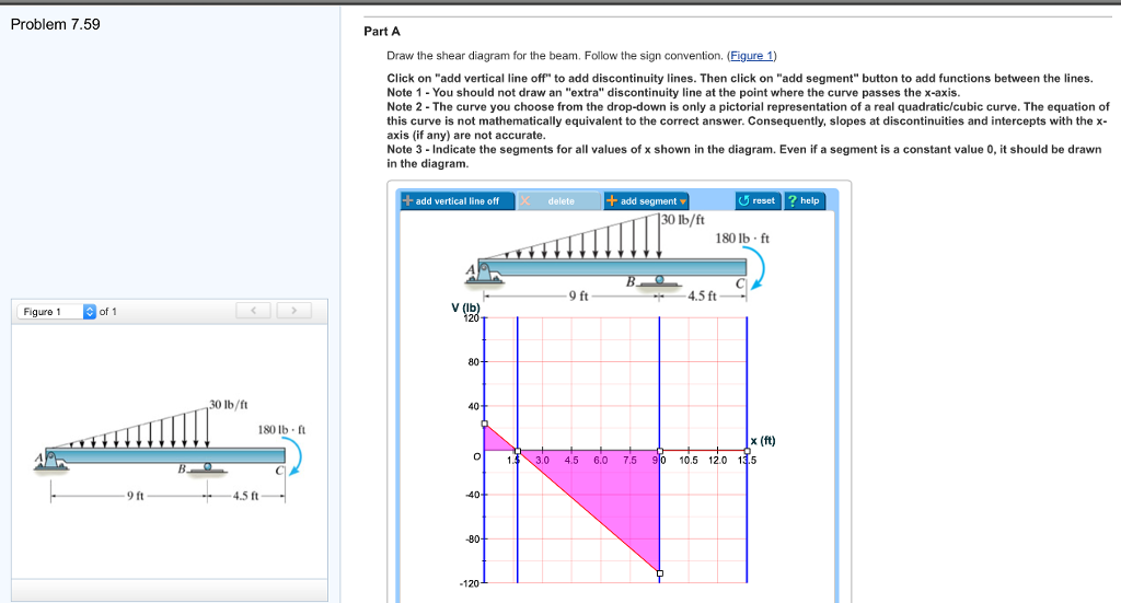
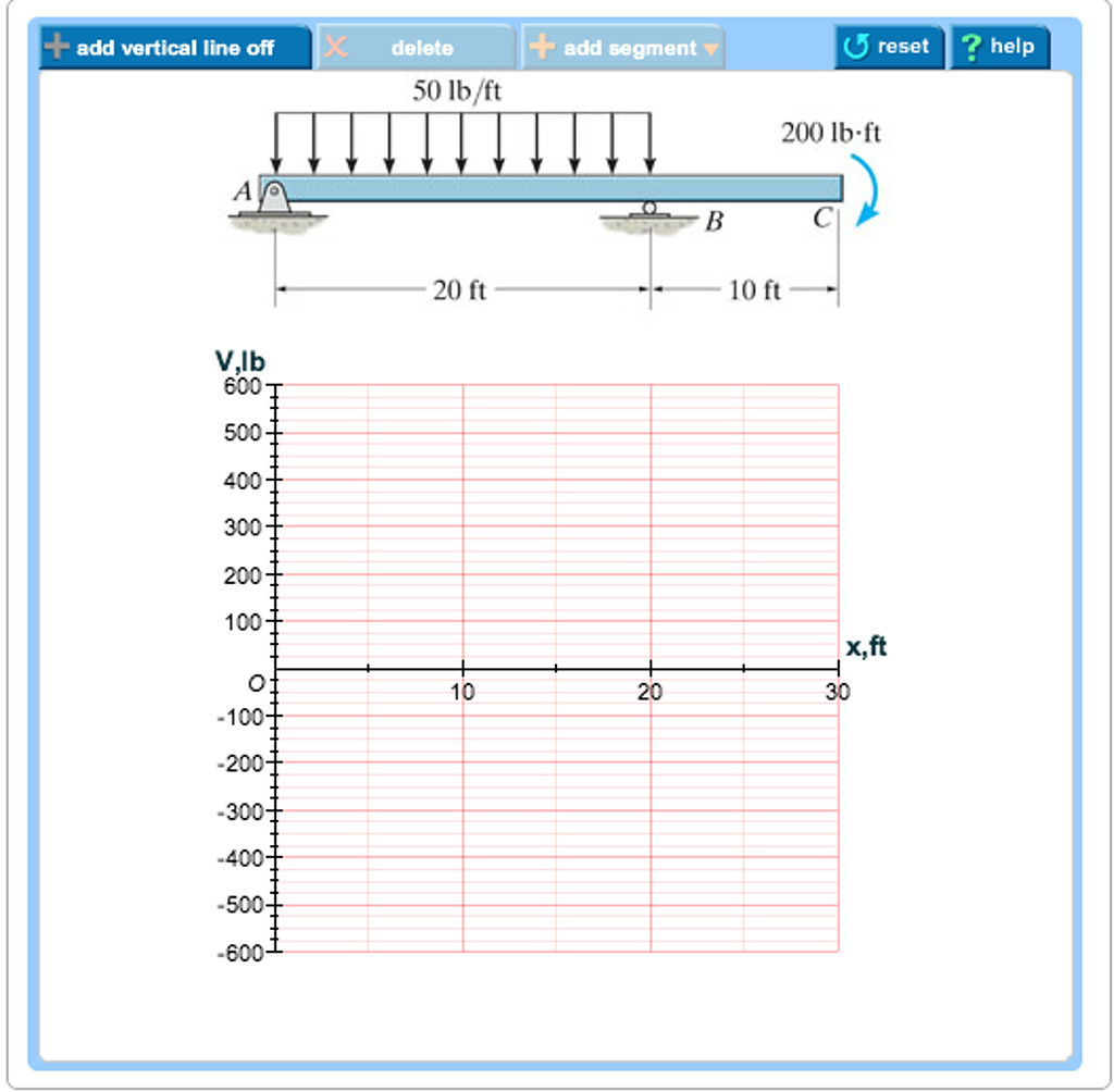
Solved Problem 7.59 Part A Draw the shear diagram for the ...
Free Online Beam Calculator | SkyCiv Engineering Free online beam calculator for generating the reactions, calculating the deflection of a steel or wood beam, drawing the shear and moment diagrams for the beam. This is the free version of our full SkyCiv Beam Software. This can be accessed under any of our Paid Accounts, which also includes a full structural analysis software.

ENGINEERING MECHANICS STATICS Pages 351-400 - Flip PDF ...
Answered: Draw the shear diagram for the beam.… | bartleby Solution for Draw the shear diagram for the beam. Follow the sign convention. Draw the moment diagram for the beam. Follow the sign convention.

How to Calculate and Draw Shear and Bending Moment Diagrams ...
Answered: DRAW THE SHEAR AND MOMENT DIAGRAMS OF… | bartleby Search concepts or drop in your homework problem! Our library grows every minute-keep searching! Engineering Civil Engineering Q&A Library DRAW THE SHEAR AND MOMENT DIAGRAMS OF THE FOLLOWING BEAMS. WRITE THE SHEAR AND MOMENT EQUATIONS USED TO DRAW THE DIAGRAMS. BEAM 1: 5 kN/m ++ x (m) 10. DRAW THE SHEAR AND MOMENT DIAGRAMS OF THE FOLLOWING BEAMS.

Draw the shear and moment diagrams for the overhang beam ...
How to draw shear force and Bending Moment Diagram of beam ... Using SW FEA 2D frame mobile application to draw shear force and Bending Moment Diagram of a beam structure.SW FEA is a finite element analysis app for the a...

Solved) - Part A Draw the shear diagram for the beam. Part B ...
Probn 4. For The Beam Shown In Figure 4, Draw The Shear ... Probn 4. For The Beam Shown In Figure 4, Draw The Shear Force Diagram And The Bending Moment Diagram. Label All Critical Values. 40 KN 60 KN/M A B60 120 KN K Am * 4m X 4m Figure 4. Beam Subjected To A Series Of Loads.
Shear Load and Bending Moment Diagrams
Answered: Draw the shear diagram of the beam… | bartleby ASK AN EXPERT. Engineering Civil Engineering Q&A Library Draw the shear diagram of the beam shown and determine the maximum shear. Incorrect diagram, no points. Show all necessary solutions. Draw the shear diagram of the beam shown and determine the maximum shear. Incorrect diagram, no points. Show all necessary solutions.
How to Draw Shear Diagrams | ReviewCivilPE
Beams – SFD and BMD
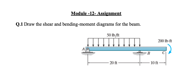
Solved) : Module 12 Assignment Q1 Draw Shear Bending Moment ...
Calculations for Shear Force and Bending Moment diagram for ...

For the figure below, draw the shear and moment diagrams for ...
How To Draw Shear Force And Bending Moment Diagram In Case Of Cantilever Beam

Draw the shear and moment diagrams for the overhanging beam ...

Draw the shear and moment diagrams for beam shown below ...
Shear and Moment Diagrams | Strength of Materials Review at ...
6.2 Shear/Moment Diagrams – Engineering Mechanics: Statics

(Solved) Problem: F6-14 (Mechanics of Materials, by R. C. ...
Solved) : Part Draw Shear Diagram Beam Follow Sign Convention ...


Comments
Post a Comment