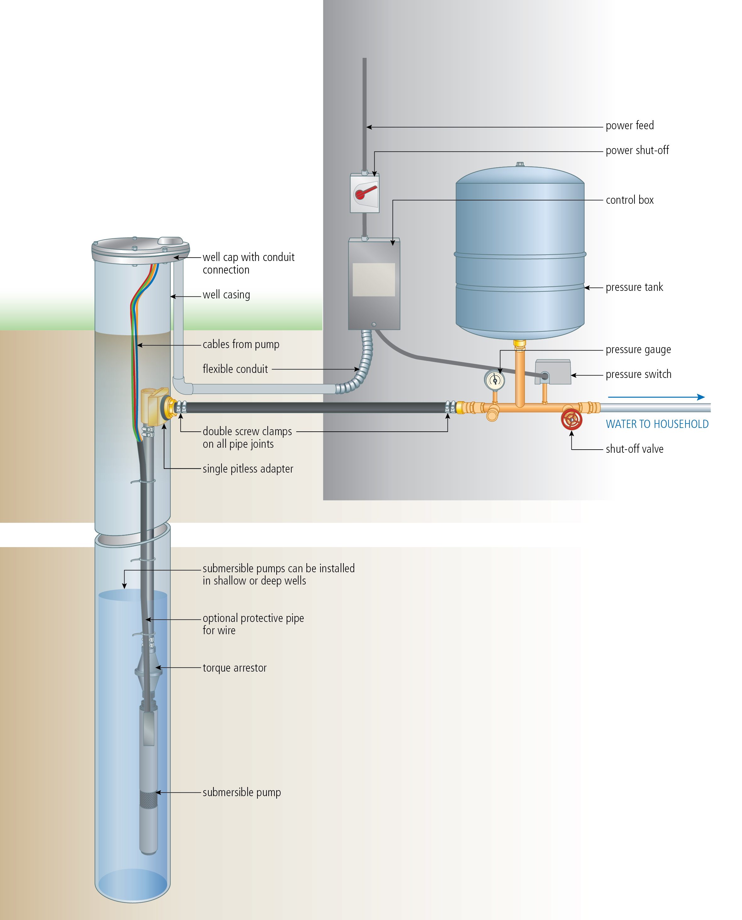
43 submersible pump installation diagram
Safe installation, operation, and maintenance of ITT Goulds Pumps equipment are an essential end user responsibility. This Pump Safety Manual identifies specific safety risks that must be considered at all times during product life. Understanding and adhering to these safety warnings is mandatory to ensure Submersible Pump Start Stop Circuit Homemade Projects. Single phase motors and controls submersible pump wiring diagram control water troubleshooting microcontroller starter circuit magnum two pumps well installation panel three duplex demand wd3p 4 boards 3 simple simplex start stop automatic controller full at best in india panels solar inverter how to wire the mppt with float switch star ...
Installation Downloads · The tripod with chain block is erected. · Unpack submersible pump and remove cable guard and strainer. · Keep the submersible motor ...

Submersible pump installation diagram
Click to watch the most complete set of submersible pump installation ... above ground storage tank diagram Well Water System, Water Pump System, ... The Red Jacket submersible turbine pump (STP) is engineered for advanced environmental protection, serviceability, safety, and flow. The Red Jacket STP fits 4-inch NPT threaded, thin-wall risers and is available in a TYPICAL SUBMERSIBLE PUMP INSTALLATION 1. We recommend the captive-air style pressure tank. It has significantly higher drawdown than a standard pressure tank and eliminates water logging problems. The air level in the tank should be 2 lbs. less than pressure switch turn-on level. For a 30-50 switch, this would be 28 lbs. of air with the tank ...
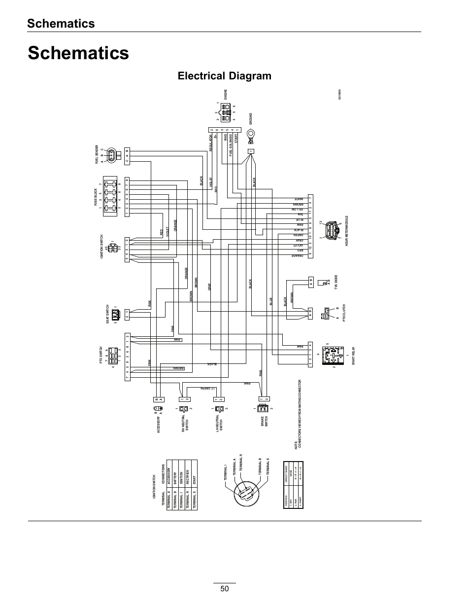
Submersible pump installation diagram. If the pump is turning backwards when it is called on to start the increased torque may cause damage to the pump motor and/or motor shaft. Install an adequately sized gate valve AFTER the check valve for pump, plumbing and check valve maintenance. Important - Before pump installation. Drill a 3⁄ 16 " (4.8mm) relief hole in the discharge pipe. Assortment of submersible pump wiring diagram. A wiring diagram is a streamlined standard pictorial depiction of an electric circuit. It shows the components of the circuit as simplified forms, and the power as well as signal connections between the gadgets. www.sulzer.com Installation, Operating and Maintenance Instructions Submersible Sewage Pump Type ABS XFP PE1-PE3 6005675 (11.08.2021) en EN 5675-L Submersible well pump wiring diagram. Here is the complete guide step by step. Assortment of submersible pump control box wiring diagram. It shows the elements of the circuit as simplified forms and also the power as well as signal links between the devices.
Typical pumps used in a submersible pump installation are either a two or three wire pump. The two wire pumps have the starting capacitor built into the submersible motor whereas the three wire pumps do not have the capacitor built into the motor, they require a control box which is normally found in the pump house at the well head. A wiring diagram is an easy visual representation in the physical connections and physical layout of an electrical system or circuit. Control Panel For 1 H P Submersible Pumps With Timer Ltems T 1050 Ewatercart Com. 4oz Bottle Round Metal 17oz Bottle Round Plastic. Duplex pump control panel wiring diagram inspirational dump trailer. Wiring Diagram For 220 Volt Submersible Pump Water Pumps Submersible Pump Submersible . Deep Well Pump Installation Instructions In 2021 Deep Well Pump Well Pump Shallow Well Jet Pump . In diagram, pump, setup, water. Leave a Reply Cancel reply. Your email address will not be published. Required fields are marked * Comment. 1 Ph Sps Cdr. Pump starter circuit single phase submersible madhav control panel 2 0 hp catalogue 2nd proof cdr panels of 1 5 the red jacket turbine float switch installation wiring cri pumps motor manufacturer all c r i catalogs and technical residential systems ph sps 3 run on general purpose from taro l t types list 2021 for have a problem we can forum sa copper deep well automatic starters ...
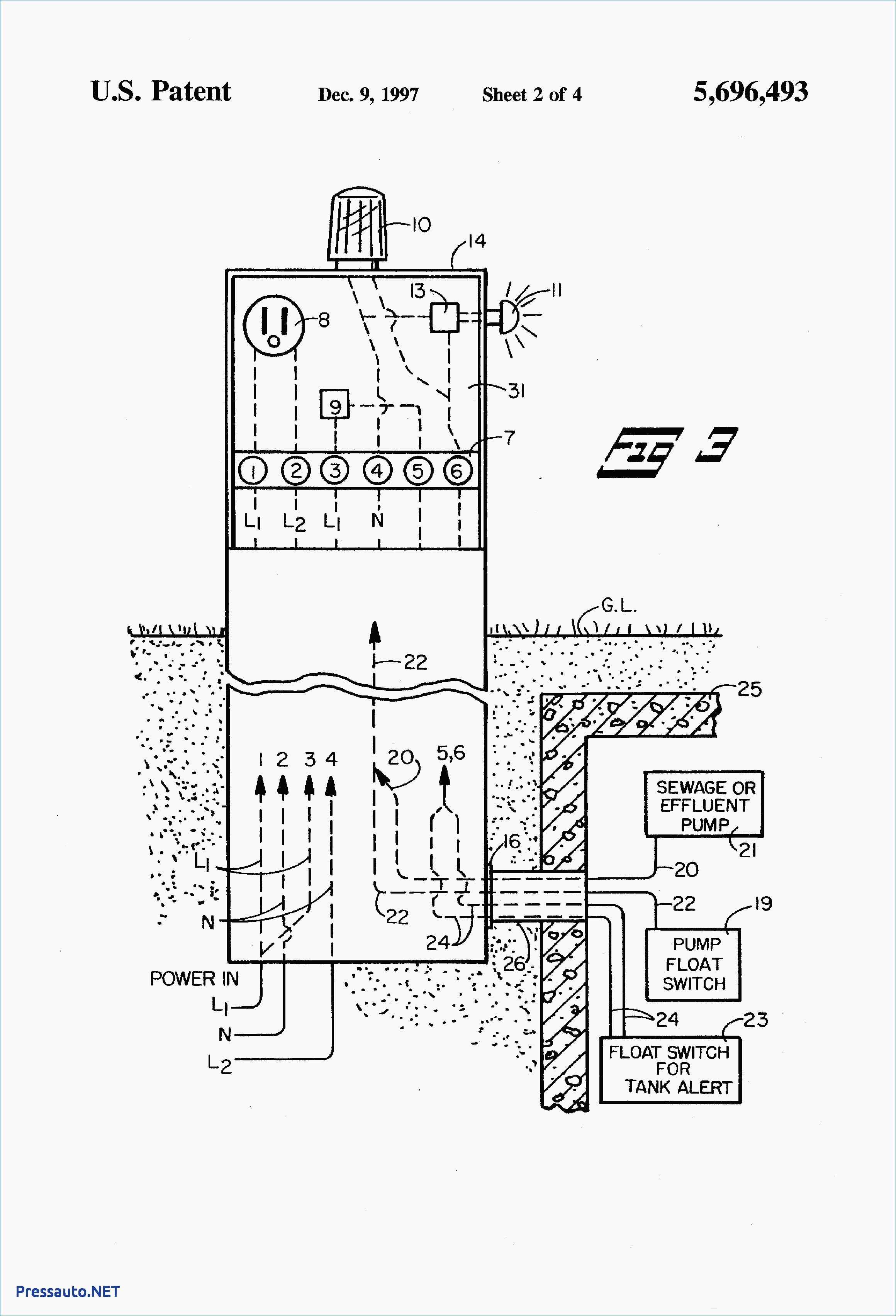
Single-phase submersible pump control box wiring diagram - 3 wire submersible pump wiring diagram In the submersible pump control box, we use a capacitor, a resit-able thermal overload, and a DPST switch (double pole single throw). The wiring connection of the submersible pump control box is very simple. Here is the complete guide step by step. Wiring Diagrams Deep Well Pump Installation 2 Wire Simple 3 - 2 Wire Submersible Well Pump Wiring Diagram. Wiring Diagram includes both examples and step-by-step instructions that might allow you to definitely truly construct your venture. This really is useful for both the people and for professionals that are searching to learn more ... Install a Submersible Pump Lesson#4: Follow These Tricks for Lowering a Submersible Pump Using a grinder to remove the sharp burr on the top edge of a steel well casing. Getting pipe and pump and wires into the well in one piece is heavy work, and there are a couple of things you can do to make success more certain. Float Switch Connection Auto Manual Single Phase Water Pump Youtube Electrical Circuit Diagram Electrical Projects Water Pumps. Wiring Diagram For 220 Volt Submersible Pump Submersible Pump 1993 Ford Mustang Wiring Diagram 2001 Ford Mus Submersible Pump Submersible Well Pump Sump Pump. 44 Luxury Single Phase Submersible Pump Starter Wiring ...

Jet Pump: Installing A Jet Pump And Pressure Tank
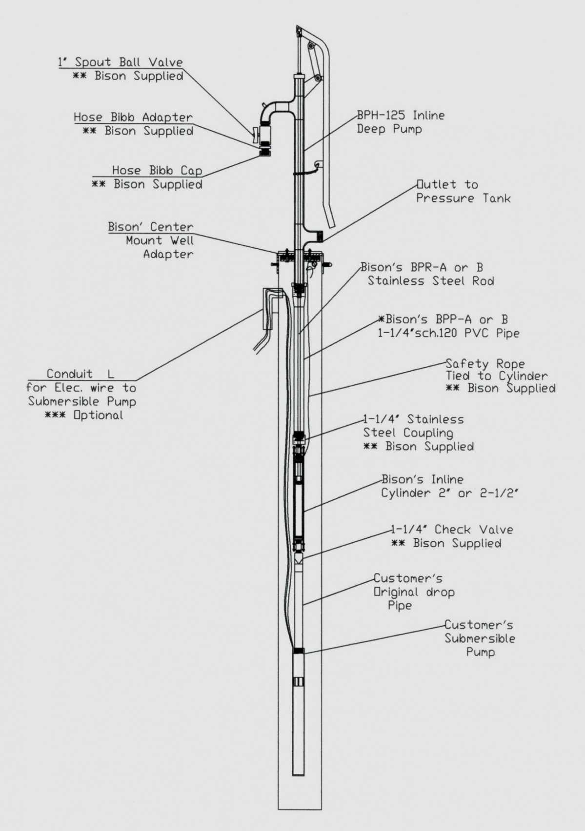
Submersible Well Pump Accessories Installation Diagram. This illustration is for educational purposes ; It is not intended as an installation guide.

3 Phase Submersible Pump Wiring Diagram with DOL Stater ...
Deep Well Submersible Pumps. Operating & Installation Instructions. CAUTION: Before operating or installing this pump, read this manual and follow all ...12 pages
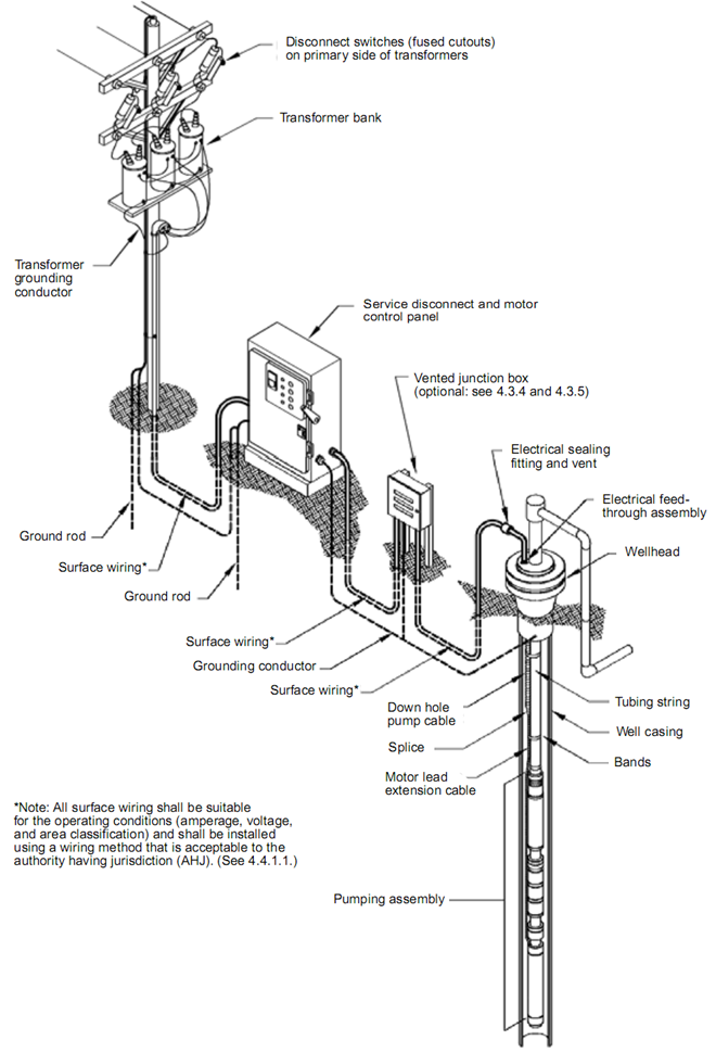
Submersible Pump System Overview: main surface and ...
tain conditions, submersible pumps can develop extremely high pressure. Install a pressure relief valve capable of passing entire pump flow at 75 PSI (517 kPa) when using an air over water pres-sure tank. Install a pressure relief valve capable of passing entire pump flow at 100 PSI (690 kPa) when using a pre-charged pressure tank.

Submersible Pump Installation Diagram - Free Wiring Diagram
For proper installation in a submersible pump application, you must strip 1/4" of insulation from the wire. The heat shrink tube is then slid over one end, the wires insert into the stakon connector. The heat shrink is then crimped to attach the stakon to the wire. Before you shrink the tube, ensure the tube is centred over the stakon connector.
2 Wire Submersible Well Pump Wiring Diagram | Wiring Diagram
Understanding Well Pump Wiring Diagrams. Learning how to read well pump wiring diagrams is necessary to install a well pump properly. Deep submersible well pumps will be either 2-wire or 3-wire well pumps, and 3-wire well pumps will need a separately installed control box. Two-Wire Well Pump Wiring Diagrams

Submersible Pump Diagram - Electrician Talk - Professional ...
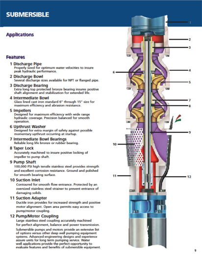
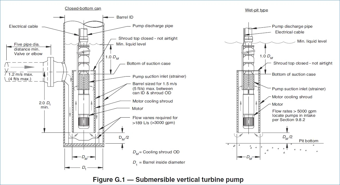
Franklin submersible motors are designed primarily for operation in the vertical, shaft-up position. During acceleration, the pump thrust increases as its output head increases. In cases where the pump head stays below its normal operating range during startup and full speed condition, the pump may create upward thrust.

person wearing silver link bracelet watch
The wiring connection of submersible pump control box is very simple. 220v 3 wire well pump wiring diagram. Red and yellow might indicate that it is a 2 wire 220 volt pump. 2 wire well pump diagrams are slightly easier to understand and are more straight forward to wire. Electrical ac dc 3 wire 240v for well pump i have a 220v water well pump ...

Submersible Pump Control Box Wiring Diagram For 3 Wire ...
INSTALLATION DIAGRAM - SURFACE PUMPS ELECTRICAL CONNECTIONS NOT SHOWN ON THIS DIAGRAM. UNIT MAY BE MOUNTED DIRECTLY ON THE SURFACE PUMP OR BETWEEN THE PUMP AND THE FIRST TAP. 17 Remove pressure switch from surface pump and wire Mascontrol directly to pump.® IMPORTANT INSTALLATION DIAGRAM - SUBMERSIBLE PUMPS

Submersible Well Pump Diagram - Hot Water Recirculating System
In addition Wiring Diagram gives you the time body during which the projects are to be completed. Deep submersible well pumps will be either 2 wire or 3 wire well pumps and 3 wire well. 3 Phase Submersible Pump Wiring Diagram with DOL Stater. As stated earlier the traces in a 240 Volt Well Pump Wiring Diagram represents wires.

green trees near river under cloudy sky during daytime
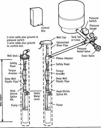
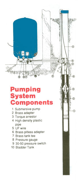
PUMP 3 1. Check Valve Located at the top of the pump to prevent back flow into pump and hold the head of water in the system. 2. Torque Arrestor Installed directly above Submersible Pump to protect pump and well components from starting torque damage. 3. Safety Rope A safety line from the top of the well to the pump. 4. Pitless Adapter

Buying A Home With A Private Well ~ Avon Real Estate
Single Phase Submersible Pump Wiring Diagram. angelo on November 9, 2021. Pressure Switch Wiring Diagram Air Compressor On 5 Gif Cool And Ingersoll Rand On Ingersoll Air Compressor Pressure Switch Air Compressor Air Compressor Switch. Wiring Diagram For 220 Volt Submersible Pump Submersible Pump 1993 Ford Mustang Wiring Diagram 2001 Ford Mus ...

3 Wire Submersible Pump Wiring Diagram - Diagram Stream
LANCASTER PUMP recommends an experienced water-well serviceman to install new water systems or replace an existing submersible water-well pump or pump motor ...6 pages

Wiring Diagram For 220 Volt Submersible Pump | Well pump ...
Dual Capacitor Wiring Diagram. Installing Profile Seals. Single Phase TP Pump Start Up Procedure. ... HOMA submersible pumps has been serving the needs of municipal and industrial wastewater customers throughout the world. Contact Info. Homa Pump Technology 390 Birmingham Blvd. Ansonia, Connecticut 06401 (203) 736-8890 (800) 452-4662

Myer Submersible Pump Wiring Diagram - Wiring Diagram
at Pump Discharge Submersible Pump Unit Suction Screen Motor Well Screen or Casing Perforations Note: Keep pump at least 5' from bottom of well and above well screen or casing perforations. FIGURE 1 - Installation Diagram Torque Arrestor

white animal skull on white surface
Control Panel For Submersible Molock Pumpset Pump Starter Circuit. Water pump wiring troubleshooting well installation single phase motors and controls everbilt 3 4 hp submersible wire using relays starter control two pumps automatic level controller for jet circuit full schematic diagram of pv pumping 2 motor 10 gpm soft potable universal rainwater a three 120v electronics 5 useful dry run ...
Deep Well Submersible Pump Installation Diagram - Food Ideas
TYPICAL SUBMERSIBLE PUMP INSTALLATION 1. We recommend the captive-air style pressure tank. It has significantly higher drawdown than a standard pressure tank and eliminates water logging problems. The air level in the tank should be 2 lbs. less than pressure switch turn-on level. For a 30-50 switch, this would be 28 lbs. of air with the tank ...

unknown
The Red Jacket submersible turbine pump (STP) is engineered for advanced environmental protection, serviceability, safety, and flow. The Red Jacket STP fits 4-inch NPT threaded, thin-wall risers and is available in a

black smartphone beside white plastic bottle and black smartphone
Click to watch the most complete set of submersible pump installation ... above ground storage tank diagram Well Water System, Water Pump System, ...
Submersible Pump Parts Diagram - Free Wiring Diagram
2 Wire Submersible Well Pump Wiring Diagram | Wiring Diagram

SUBMERSIBLE PUMPS BASIC INFORMATION AND DIAGRAM ~ KW HR ...

Single Phase Submersible Pump Panel Wiring Diagram ...
Deep Well Submersible Pump Installation Diagram - Food Ideas

Submersible Pumps – Danforth Solar – Malawi
Well & Septic Systems Diagnostics - Monticello Well Pump ...
Deep Well Submersible Pump Installation Diagram - Food Ideas

2 Wire Submersible Well Pump Wiring Diagram Gallery

Beauchamp Water Treatment Blogspot: Submersible Well Diagrams

Submersible Well Pumps Install Example. Typical Example of ...

How well water pump and pressure systems work? | Clean ...
Submersible Pump Installation Diagram - Diagram Resource ...

Clean Well Water Report: Well Pump & Pressure Tank Diagram

Submersible pump control box wiring diagram in বাংলা ...
Square D 9013fsg2 Wiring Diagram

Gallery Of Goulds Submersible Pump Wiring Diagram Download

3 Wire Submersible Pump Wiring Diagram - Diagram Stream

human fist photography

Deep Well Pump Installation Diagram — UNTPIKAPPS
INSTALL A SUBMERSIBLE PUMP: 6 Lessons for doing it right

man in black cap and black shorts standing on road during daytime

two men standing and throwing rope on sea

Zoeller Sump Pump Wiring Diagram - Wiring Diagram Schemas

Submersible Well Pump Accessories Installation Diagram


Comments
Post a Comment