43 fire alarm horn strobe wiring diagram
Strobe designs are constant wattage and the maximum RMS current rating occurs at the lowest allowable operating voltage. (RMS is root mean square and refers to the effective value of a varying current waveform.) 3. Terminals are provided for wiring the horn and strobe of these A/Vs to separate NACs. Operation of the horn and strobe China Ul Listed Fire Alarm System Wall Ceiling Mounted Strobe For Indoor Use Applications Dt981w Dt982w Horn. China Ul Listed Intelligent Addressable 4 Loops 1008 Devices Fire Alarm Control Panel Model Dt106. Free pdf diagram class a wiring and b module e part 1 electrical exam prep what is conventional fire wire contractor magazine alarm ...
Jul 22, 2020 · Fire Alarm Strobe Wiring Diagram | Manual E-Books – Fire Alarm Horn Strobe Wiring Diagram Wiring Diagram contains several detailed illustrations that display the link of varied products. It includes directions and diagrams for various varieties of wiring methods as well as other items like lights, home windows, and so on.

Fire alarm horn strobe wiring diagram
fire alarm horn strobe wiring diagram – What’s Wiring Diagram? A wiring diagram is a form of schematic which uses abstract pictorial symbols to exhibit every one of the interconnections of components in a system. Mar 09, 2018 · fire alarm horn strobe wiring diagram – Building circuitry diagrams show the approximate locations and also affiliations of receptacles, lights, as well as irreversible electrical services in a building. Interconnecting cable courses might be revealed roughly, where specific receptacles or fixtures should get on a common circuit. Fire Alarm Horn Strobe Wiring Diagram designed to provide audible and visual signals for Fire Alarm. Protection CSH24W combines a selective 2 tone horn with a colored light. Select-A-Strobe. the strobes remain flashing, Refer to the wiring diagram Fig.1 yr dBA refer to Table 1.
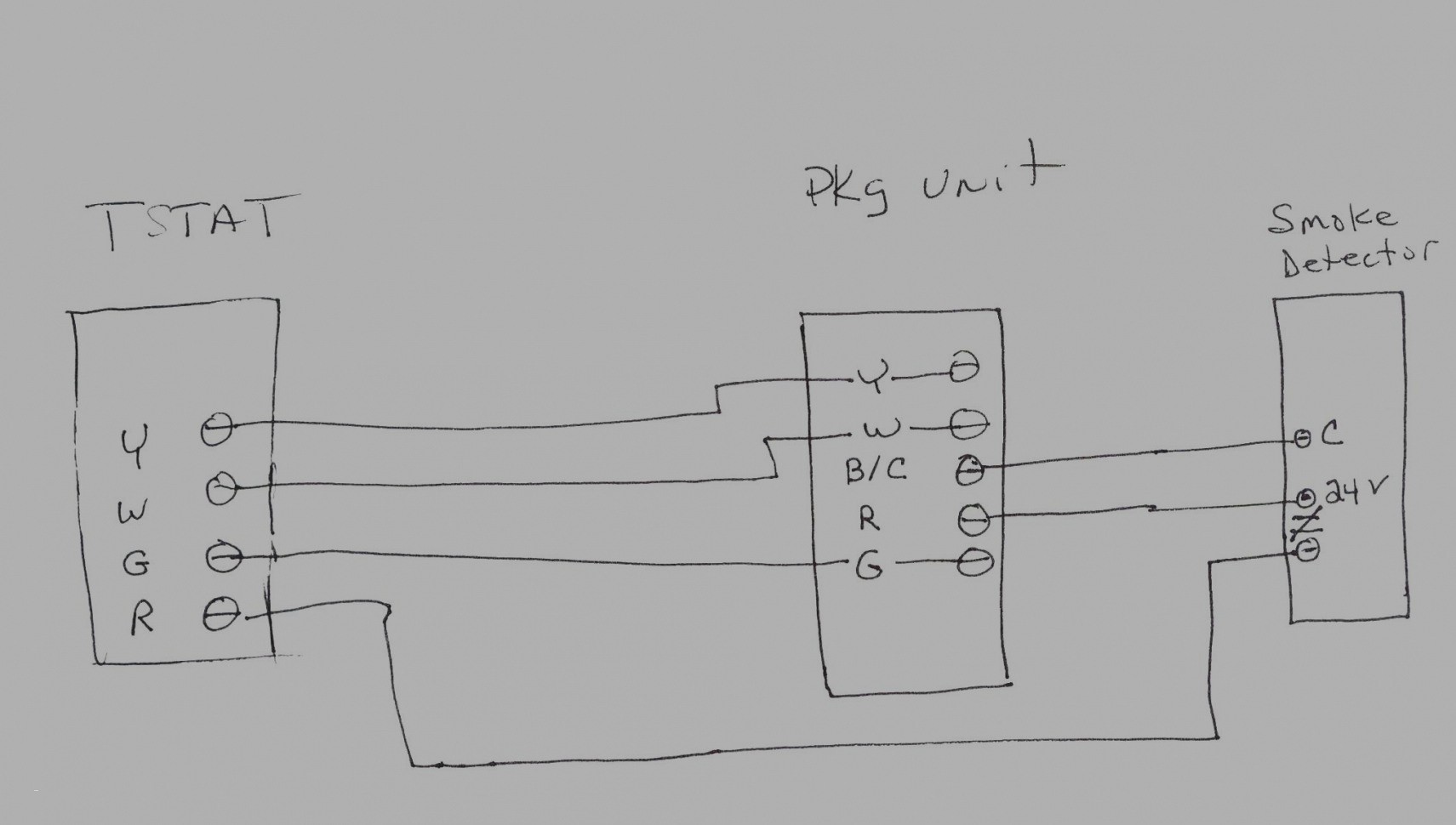
Fire alarm horn strobe wiring diagram. All horn and strobes shall be wired on alternate circuits. If no FIRE occurs the thermistor will remain at 10 K. Simple Fire Alarm Circuit Using Thermistor Germanium Diode And Lm341 Fire Alarm Circuit Diagram Circuit Install an alarm bell back box and the fire to my house is bells installation sheet automatic alram circuit […] Assortment of fire alarm horn strobe wiring diagram. Fire alarm wiring diagram. It reveals the elements of the circuit as simplified shapes and the power and signal links in between the tools. A wiring diagram is a streamlined standard pictorial representation of an electric circuit. Otherwise the arrangement will not work as it should be. According to previous, the traces in a Fire Alarm Horn Strobe Wiring Diagram signifies wires. Occasionally, the cables will cross. But, it does not mean connection between the wires. Injunction of 2 wires is generally indicated by black dot at the junction of two lines. There will be main lines that are represented by L1, L2, L3, and so on. Fire Safety Signaling Devices Are Covered Under Title III The ADA comprises four titles that define and prohibit discrimination on the basis of disabilities within specific areas. Fire safety signaling devices are addressed under Title III, which covers public accommodations and services, including transportation. Compliance is enforced by the
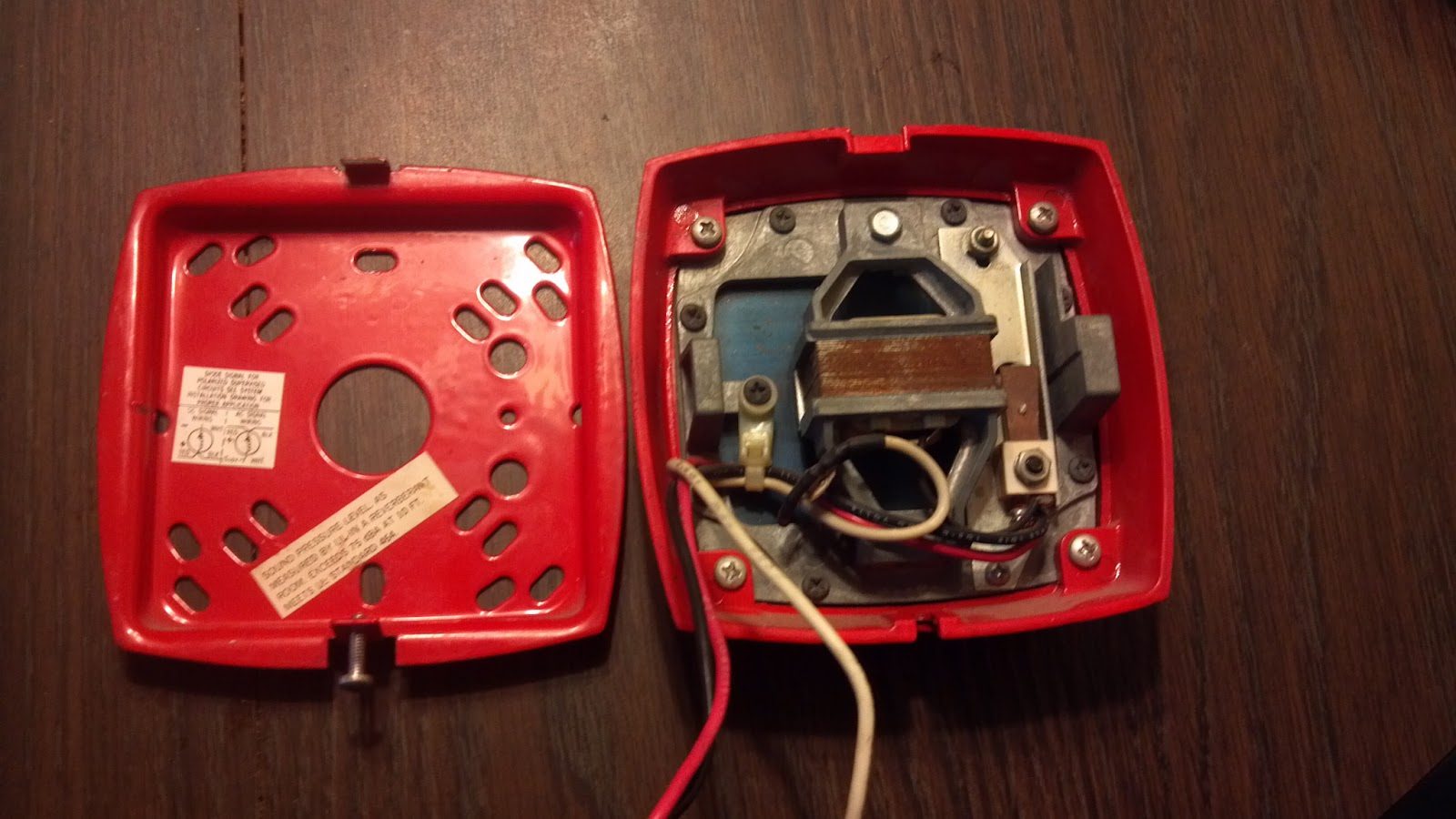
Refer to the appropriate fire alarm control panel manufacturer or power supply for more information. System Sensor wall 2-wire horn strobes, 2-wire chime ...4 pages NOTICE: This manual shall be left with the owner/user of this equipment. Fire Alarm System Considerations. Temporal and Non-Temporal Coded Signals: The American ...4 pages 12VDC 2-wire horn/strobe current is shown in Figure 1D. 24VDC 2-wire horn/strobe current is shown in Figure 1E. Current draw for other horn/strobe power supplies can be calculated by adding the strobe current draw (Figure 1A) for chosen candela set-ting to the horn current draw (Figure 1C) for chosen setting. Figure 1D: 12VDC Horn/Strobe ... Fire Alarm Horn Strobe Wiring Diagram Image What is a Wiring Diagram? A wiring diagram is a simple visual depiction of the physical links as well as physical layout of an electrical system or circuit. It reveals just how the electric wires are interconnected and can also show where components and parts could be connected to the system.
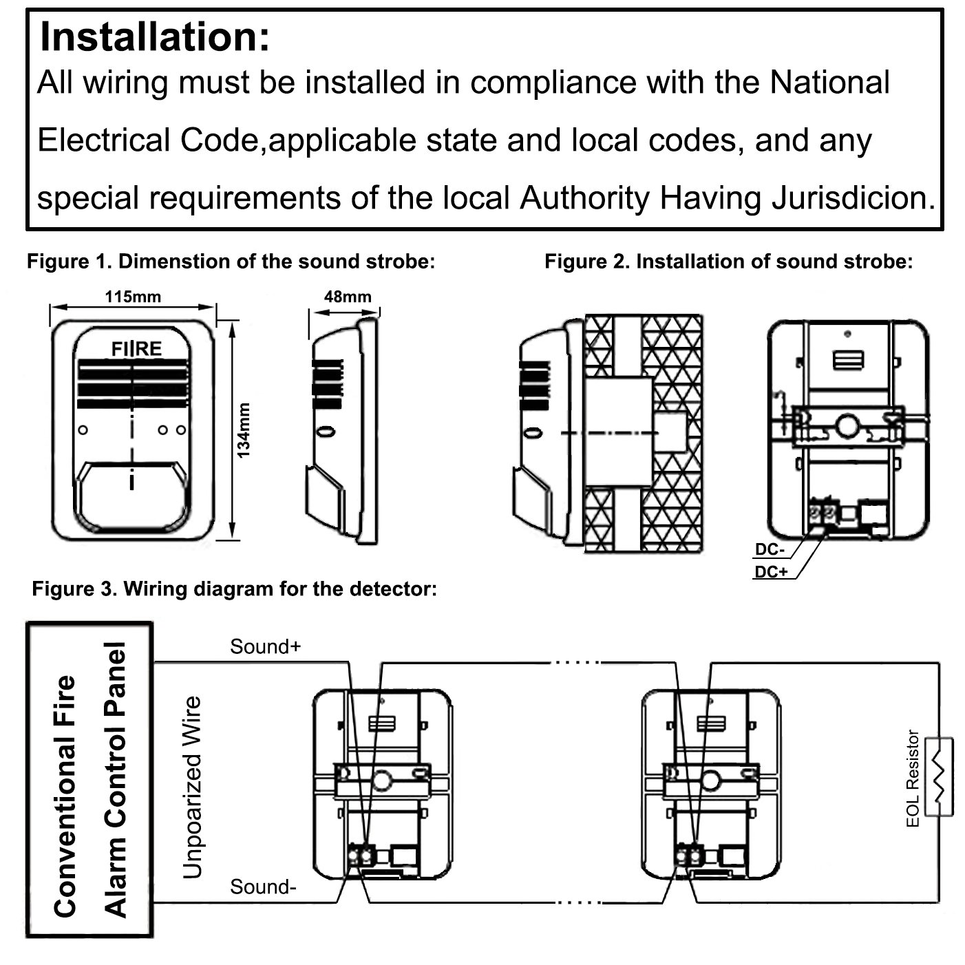
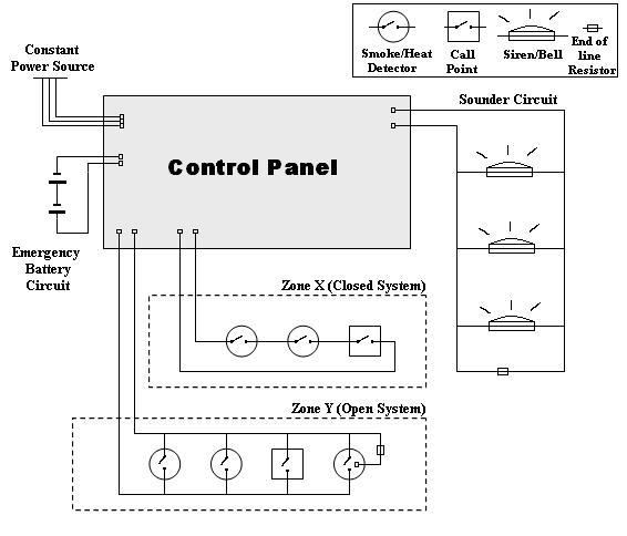
Related Post: Difference Between Conventional and Addressable Fire Alarm; Wiring Diagram of Heat Detector in Home (AC) Conventional Fire Alarm System. In a conventional fire alarm system, all devices such as detectors, sounders and call points are connected to the control panel through separate wire or cable instead of shared one. Oct 13, 2020 - Fire Alarm Horn Strobe Wiring Diagram . Fire Alarm Horn Strobe Wiring Diagram Best Of. Fire Alarm Horn Strobe Wiring Diagram Image. Audible Signaling Appliance for Fire Alarm Service. INST. SHT. NO.SH1224-H1043 S101207a. Wall Mount Combination Strobe Horn. HORN/STROBE. FHS-340 INDOOR.4 pages Fire Alarm Strobe Light Wiring Diagram. Is this an addressable 4 wire speaker strobe china ul listed fire alarm system wall ceiling mounted for indoor use applications dt981w dt982w horn cft 991 professional conventional and intelligent alarms why won t the added horns strobes work systems 1 overview steemit protection technicians network ...
Strobe Wiring Diagram
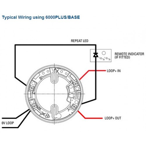
horn/strobe control or with TrueAlert addressable control; for horn/strobe appliance applications, use 4-wire appliances (see data sheet S4903-0011), for horn control, select horn operation as free-run Wire Connections Screw terminals for in/out wiring, 18 to 12 AWG wire (0.82 mm2 to 3.31 mm2)

Fire Alarm Horn Strobe Wiring Diagram - Wiring Diagram
2 Oct 2018 — Refer to the appropriate fire alarm control panel manufacturer or power supply for more information. System Sensor wall 4-wire horn strobes ...4 pages

Fire Alarm Horn Strobe Wiring Diagram | Free Wiring Diagram
Refer to the appropriate fire alarm control panel manufacturer or power supply for more information. System Sensor ceiling 2-wire horn strobes, 2-wire chime ...4 pages

Fire Alarm Strobe Light Wiring Diagram | Shelly Lighting
I will add if you are sizing boxes for fire alarm devices go big, pushing horn strobes into place that could have eight 14 or 12 AWG solid conductors connected to it is no joy if the box is tight. It also makes a ground fault more likely Solid is a standard job spec in this area for fire alarm conductors, I don't know why.

Fire Alarm Horn Strobe Wiring Diagram - Drivenheisenberg
Fire Alarms Explained is a series where Zach discusses basic concepts of fire alarm systems, as well as showing the specific systems hands on. This is a new ...
Fire Alarm Amplifier Strobe Wiring Diagram
connection of alarm transmission wiring, communications, signaling, and/or power. If detectors are not so located, a developing fire may damage the alarm system, compromising its ability to report a fire. Audible warning devices such as bells, horns, strobes, speakers and displays may not alert people if these devices are

Wiring Diagram For Fire Alarm Pull - Complete Wiring Schemas
FIRE ALARM SECURITY ACCESS CONTROL CCTV ... Wiring diagrams provided herein are for information and reference only and are not to be used for installation purposes. ... Integrity: Horns, Horn-strobes: 757 Series 54 Hazardous Location Notification Appliances 55.
4 Wire Fire Alarm Wiring Diagram Strobe Panic
Fire Alarm Horn Strobe Wiring Diagram. Best Of- Allowed to my own website, within this period I am going to explain to you in relation to fire alarm horn strobe wiring diagram. . And today, this is the 1st picture: Fire Alarm Horn Strobe Wiring Diagram Image from fire alarm horn strobe wiring diagram , source:magnusrosen.net.
Fire Alarm Horn Strobe Wiring Diagram | Wiring Diagram
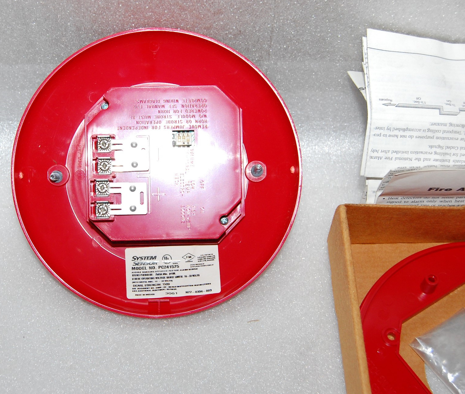
System Sensor PC2WL. The System Sensor L-Series offers the most versatile and easy-to-use line of horns, strobes, and horn strobes in the industry with lower current draws and modern aesthetics. With white and red plastic housings, wall and ceiling mounting options, System Sensor L-Series can meet virtually any application requirement.

35 Fire Alarm Pull Station Wiring Diagram - Wiring Diagram ...
Jul 23, 2020 · Fire Alarm Strobe Wiring Diagram | Manual E-Books – Fire Alarm Horn Strobe Wiring Diagram Wiring Diagram contains several detailed illustrations that display the link of varied products. It includes directions and diagrams for various varieties of wiring methods as well as other items like lights, home windows, and so on.

Home Alarm Siren Wiring
Indicating Appliance Circuits connect the fire alarm panel to the components which alert building occupants of the fire, i.e., bells, horns, speakers, strobe lights, etc. The following illustrations show schematics, wiring connections, riser diagram, and wire pull, for some commonly used fire alarm circuits.
Fire Alarm Horn Strobe Wiring Diagram - General Wiring Diagram
Fire Alarm Horn Strobe Wiring Diagram - fire alarm horn strobe wiring diagram, Every electrical structure is made up of various unique components. Each part ought to be set and linked to other parts in specific way. Otherwise, the structure won't function as it should be.
Fire Alarm Amplifier Strobe Wiring Diagram
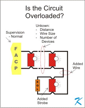
Adding just one more strobe to a fire alarm circuit isn't a problem if the installer knows exactly the strobes that are there already, and the exact length and gauge of the wire. The power supply itself might not be a problem, but the circuit should be calculated using the manufacturer's specifications. Just because the added strobe flashes ...
Wiring Ideas
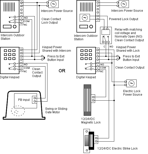
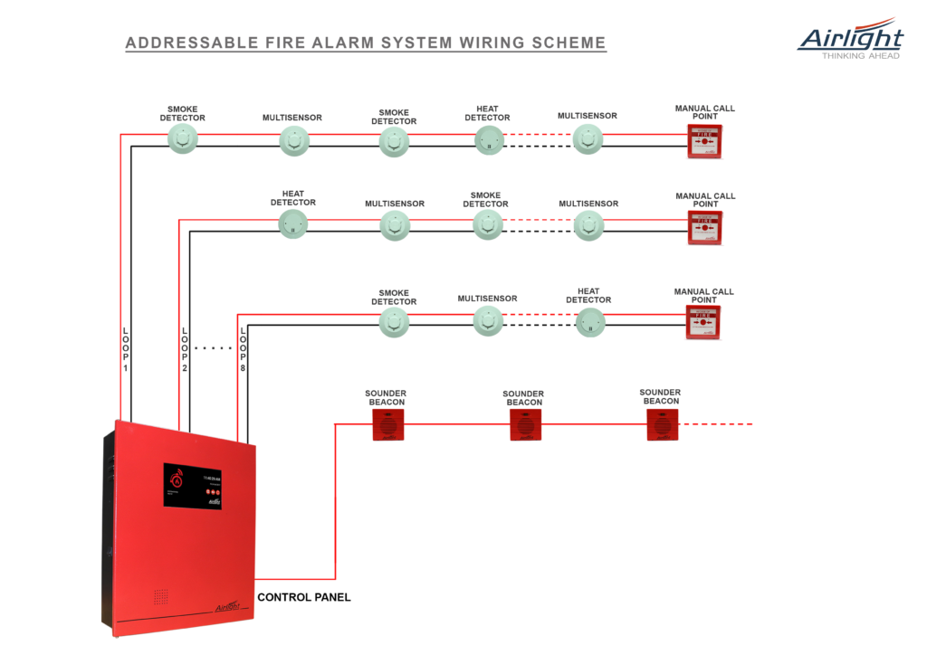
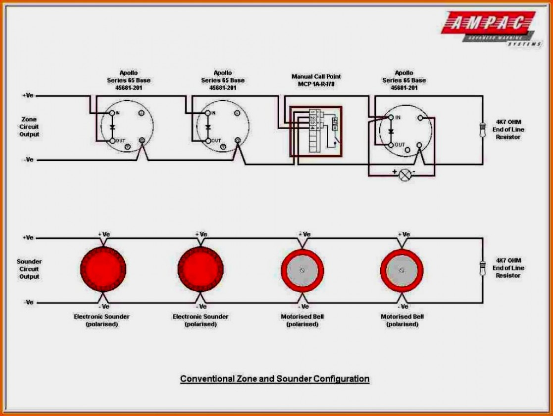
In the fire alarm industry there are three types of fire alarm wiring circuits. Below is a circuits diagram that displays the circuit styles of a Notification Appliance Circuit (NAC). This would be your horn/strobe or speaker circuits off of remote power supplies, addressable fire alarm panels, signal modules, bell cards, etc.

Fire Alarm System Diagram Advanced Axis AX | Fire Alarm ...
Types Notification Appliance Circuits/Control Circuits (NAC) Supervised polarity reversing power circuits for Horns, Strobes, Bells, Chimes Any NAC that does not have a Notification Appliance attached shall be considered a Control Circuit Performance shall be based upon wiring Class (Note the old Class & Style has been replaced with Class only)

Fire Alarm Pull Station Wiring Diagram | Free Wiring Diagram
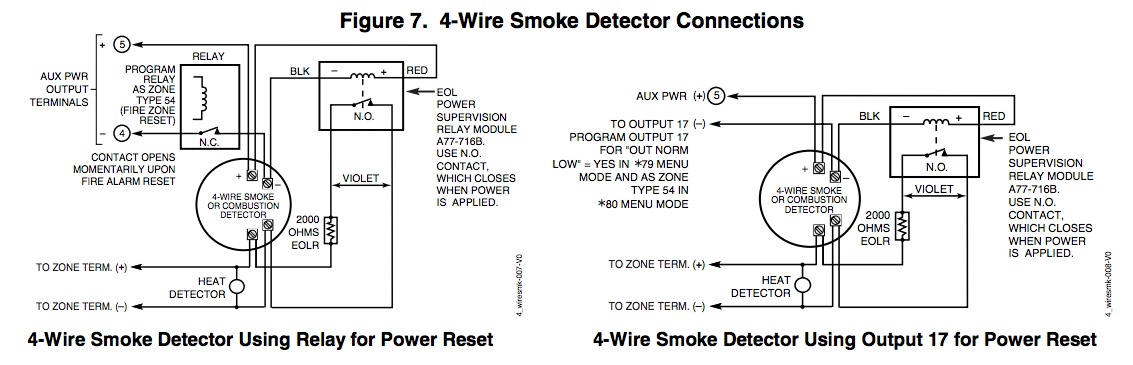
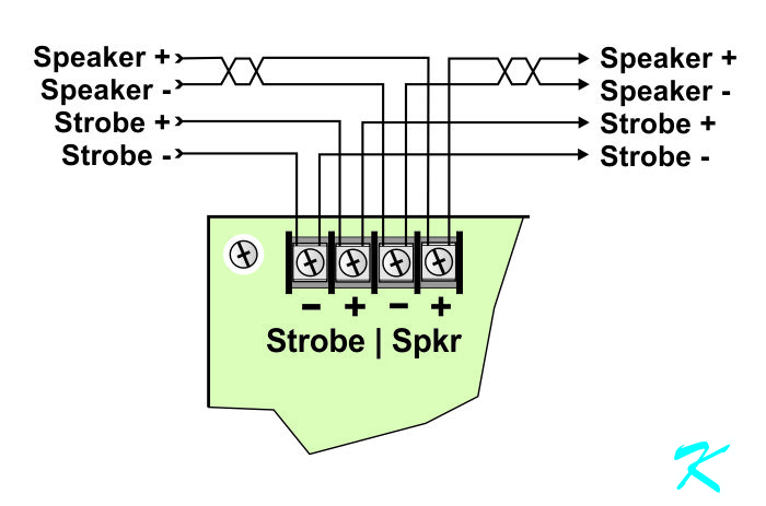
ible with the previous generation of SpectrAlert notification appliances. Horn/ strobe products are available in two versions. The 2-wire products fit systems where a single NAC controls both horn and strobe. The 4-wire products are in - tended for systems which have separate wiring circuits for the horn and strobe.

Honeywell Fire Alarm Wiring Diagram
An addressable 4 wire speaker strobe china ul listed fire alarm system wall horn cft 991 manual station why won t the added horns and strobes work wiring diagram sensor light lite how to install rm4 smart relay Is This An Addressable 4 Wire Speaker Strobe China Ul Listed Fire Alarm System Wall Ceiling Mounted Sounder Horn… Read More »
EG1F-HDVM Kidde | Hi/Lo Temporal Horn & Strobe | Valin
Fire Alarm Horn Strobe Wiring Diagram designed to provide audible and visual signals for Fire Alarm. Protection CSH24W combines a selective 2 tone horn with a colored light. Select-A-Strobe. the strobes remain flashing, Refer to the wiring diagram Fig.1 yr dBA refer to Table 1.

Fire Alarm Strobe Light Wiring Diagram | Shelly Lighting
Mar 09, 2018 · fire alarm horn strobe wiring diagram – Building circuitry diagrams show the approximate locations and also affiliations of receptacles, lights, as well as irreversible electrical services in a building. Interconnecting cable courses might be revealed roughly, where specific receptacles or fixtures should get on a common circuit.

34 Strobe Light Wiring Diagram - Wiring Diagram Database
fire alarm horn strobe wiring diagram – What’s Wiring Diagram? A wiring diagram is a form of schematic which uses abstract pictorial symbols to exhibit every one of the interconnections of components in a system.
4 Wire Fire Alarm Wiring Diagram Strobe Panic

32 Fire Alarm Horn Strobe Wiring Diagram - Free Wiring ...

Simplex Horn Strobe Wiring Diagram - Complete Wiring Schemas
Fire Alarm Horn Strobe Wiring Diagram - Derslatnaback
Flow and Tamper Switches | Fire Alarms Boston
4 Wire Fire Alarm Wiring Diagram - Wiring Diagram
25 Fire Alarm Horn Strobe Wiring Diagram - Wiring Database ...

Fire Alarm Horn Strobe Wiring Diagram - Diagram For You

Fire Alarm Horn Strobe Wiring Diagram | Wiring Diagram
32 Fire Alarm Horn Strobe Wiring Diagram - Free Wiring ...

Wiring Diagram For Fire Alarm Pull - Complete Wiring Schemas

Fire Alarm Strobe Light Wiring Diagram | Shelly Lighting
4 Wire Fire Alarm Wiring Diagram Strobe Panic
Fire Alarm Horn Strobe Wiring Diagram | Cadician's Blog

32 Fire Alarm Horn Strobe Wiring Diagram - Free Wiring ...

Fire Alarm Horn Strobe Wiring Diagram
Planning a Security System / Burglar Alarm
Fire Alarm Horn Strobe Wiring Diagram | Cadician's Blog
Fire Alarm Horn Strobe Wiring Diagram

Fire Alarm Strobe Light Wiring Diagram - Wiring Diagram

Commercial Fire Strobe Wiring | schematic and wiring diagram
Addressable Fire Alarm System Diagram - The O Guide

Wiring Diagram Fire Alarm Addressable • Patigeni


Comments
Post a Comment