43 battery charger diagram
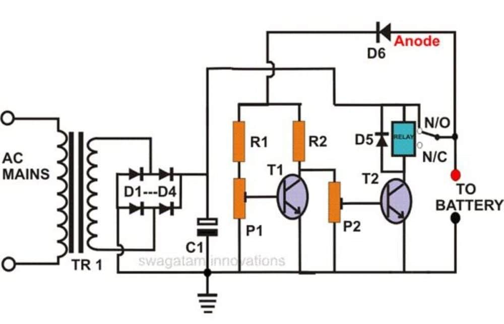
A good designed circuit of a Alkaline battery charger. ... This is a circuit of dc to dc converter, this is a versatile circuit and can be use for many purposes in this diagram LT1073 is used for 1.5 volt to 5 volt conversion, voltage can be taken from any … 05-02-2012 · Battery charger circuit applications are ideally suited with this IC and we are going to study one example circuits for making a 12 volt automatic battery charger circuit using the IC LM338. Referring to the circuit diagram we see that the entire circuit is wired around the IC LM301, which forms the control circuit for executing the trip off actions.
TI’s BQ25890 is a I2C 1cell 5A buck battery charger Maxcharge™ tech for high input with D+/D-. Find parameters, ordering and quality information
Battery charger diagram
30 Mar 2021 — The charging current rate is the most important factor which significantly influences the behaviour of the battery. It is a simple method that ... 21-11-2021 · Single-battery and charger application. The main components of the system are the battery, charger, and distribution switchboard including the DC system monitoring relay. Figure 1 shows the mainline diagram of a single battery and charger application. 02-09-2020 · Power Supply for ESP32 with Battery Charger & Boost Converter. The Circuit Diagram for Power Supply Circuit for ESP32 with Battery Charger & Boost Converter is given below. The circuit can be powered using two methods, one with 9V/12V DC Adapter and other with 3.7V Lithium-Ion Battery.
Battery charger diagram. Varying the 5k pot enables setting of any desired constant voltage across the C2 capacitor (Vout) which can be used for charging a connected battery across ... How to make a 12V battery charger at home? Description Here is the circuit diagram of a simple and straight forward 12 V battery charger circuit with diagram.This circuit can be used to charge all type of 12V rechargeable batteries including car batteries. May 15, 2020 - Simple 12 volt battery charger circuit diagram designed by using few easily available components, and this circuit is suitable for different ... This diagram shows the whole connection of the DC-DC On-Board Battery Charger. NOTE If you have any questions regarding this product, please call us at 1 (909) 287-7111 or or submit a ticket for troubleshooting assistance.
Charging current as well as the power to the circuit is obtained from a 0-18 volt 2 Ampere step-down transformer. The low voltage AC is rectified by the bridge ... 1 Jun 2021 — Charging batteries is simple (in theory) – put a voltage across the terminals and the battery charges. If safe charging, fast charging ... 11-08-2015 · Mobile phones generally charge with 5v regulated DC supply, so basically we are going to build a circuit diagram for 5v regulated DC supply from 220 AC. This DC supply can be used to charge mobiles as well as the power source for digital circuits, breadboard circuits, ICs, microcontrollers etc. 16 Apr 2021 — After a fully discharged LiPo battery is connected to the charger, the first stage is a pre-charge stage. During this stage, the charge current ...
02-09-2020 · Power Supply for ESP32 with Battery Charger & Boost Converter. The Circuit Diagram for Power Supply Circuit for ESP32 with Battery Charger & Boost Converter is given below. The circuit can be powered using two methods, one with 9V/12V DC Adapter and other with 3.7V Lithium-Ion Battery. 21-11-2021 · Single-battery and charger application. The main components of the system are the battery, charger, and distribution switchboard including the DC system monitoring relay. Figure 1 shows the mainline diagram of a single battery and charger application. 30 Mar 2021 — The charging current rate is the most important factor which significantly influences the behaviour of the battery. It is a simple method that ...
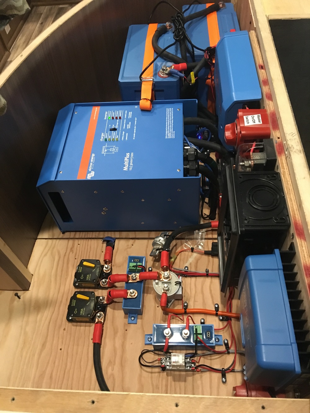
7/22/2016 – 2016 Winnebago Trend 23B, 23'

48V Solar Battery Charger Circuit with High/Low Cut-off ...

body of water under cloudy sky during daytime
12v, 7Ah Smart Battery Charger with PCB Diagram ...

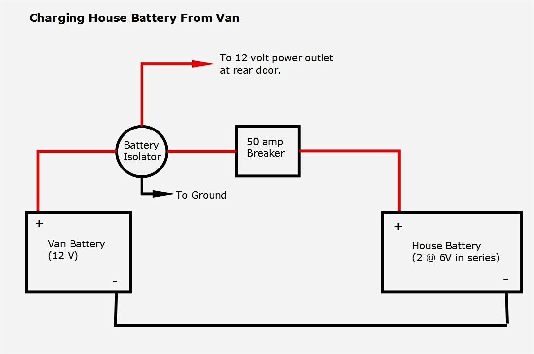
Wiring in a battery charger with dual batteries. - Boating ...

Hertner Battery Charger Wiring Diagram
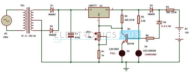
Automatic 12v Portable Battery Charger Circuit using LM317

Diehard Battery Charger Wiring Diagram - Wiring Diagram

Schumacher Battery Charger Se-82-6 Wiring Diagram

Desulfator Circuit Board (How To Order) - YouTube

photo of Golden Gate Bridge

brown concrete building near body of water during daytime
Century Battery Charger Wiring Diagram - Diagram Resource ...

Get Generac Battery Charger Wiring Diagram Download

Schumacher Battery Charger Wiring Schematic | Free Wiring ...

Simple Battery charger Circuit Diagram | Electronic ...

Automatic Car Battery Charger Schematic Circuit Diagram
how to make a 12v battery charger

blue and white concrete building under blue sky

12 Volt 10 Amp Transformer Battery Charger Circuit Diagram ...
Self Regulating Lead Acid Battery Charger Circuit ...

Automatic Battery Charger Circuit Diagram | Circuit Diagramz

cars on road near high rise buildings during daytime
Basic Rv Battery Charger Options - Rvshare - Rv Converter ...
Circuit diagram of a fundamental Battery charging system ...
Schumacher Battery Charger Wiring Diagram Se-3010

Battery Solutions: How to make a car battery charger and ...

Li-Ion Battery Charger Circuit Using IC 555 | Circuit ...

Energy Saving: Schematic diagram solar battery charger Diy

black and red bmw m 3 coupe

Automatic Battery Charger Circuit projects - ElecCircuit.com
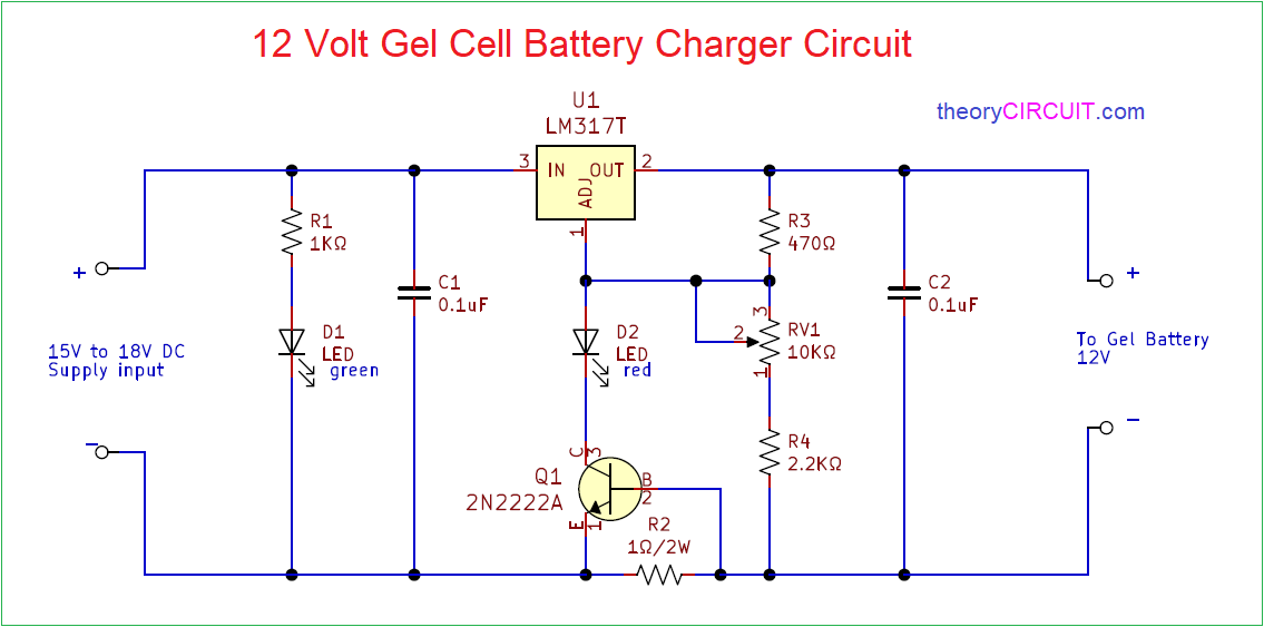
12 volt gel cell battery charger circuit diagram ...

NiMH Battery Charger Circuit Diagram

architectural photography of bridge

NiCd Battery Charger Schematic | Circuit Diagram

Solar-powered Battery Charger Schematic Circuit Diagram

NiCd Battery Charger | Xtreme Circuits

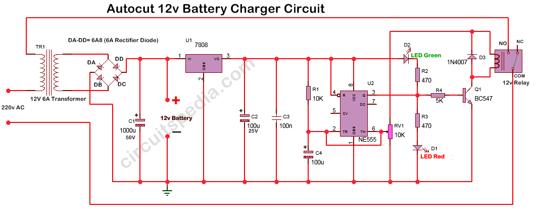
How To Make 12 Volt Automatic Cut Off Battery Charger ...

Automatic NiCd battery Charger Circuit Diagram

Cllena Dual Usb Socket Charger Wiring Diagram | USB Wiring ...

11+ Wiring Diagram Schumacher Battery Charger Schematic Gif
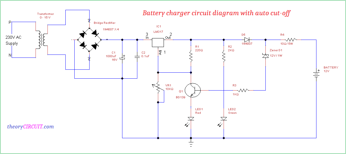
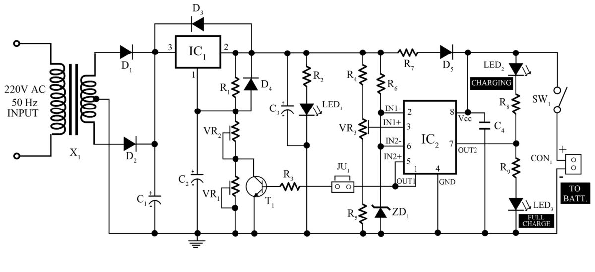
Battery charger circuit diagram with auto cut-off
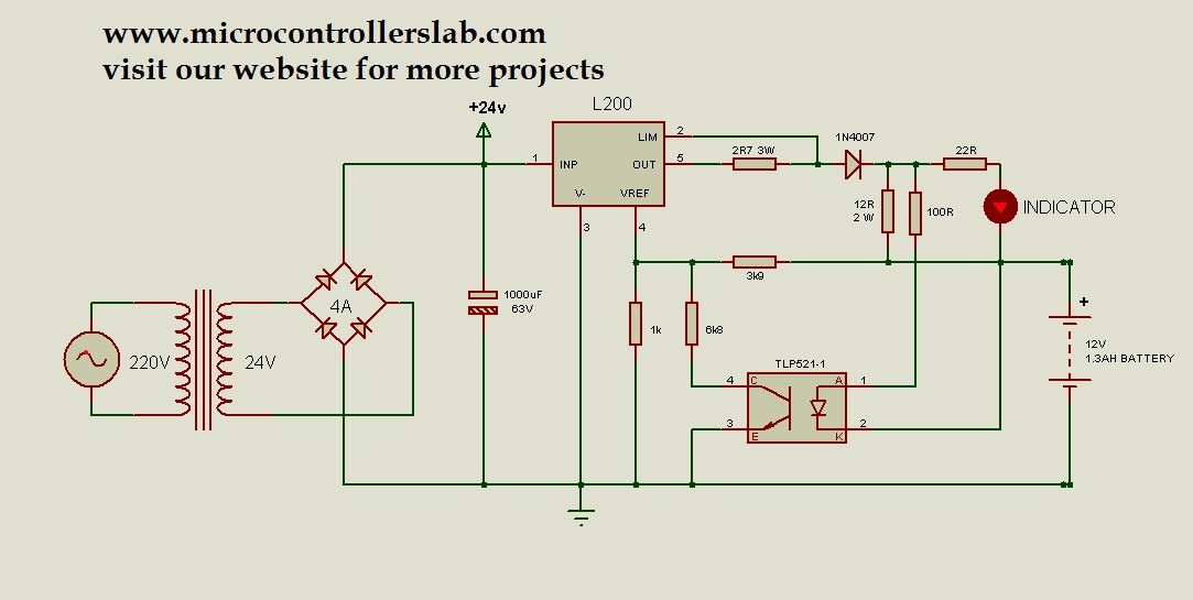
12 volt 1.3AH battery charger circuit diagram


Comments
Post a Comment