42 split phase motor diagram
Operation of Split-Phase Induction Motor When the starting winding of the motor is connected to the source of single-phase AC supply, the starting winding carries a current Is while the main winding carries a current Im as shown in the connection diagram. As the starting winding is made highly resistive whereas the main winding highly inductive. C34. K. Sairam, Srikara Reddy G, and R. Sudharshan Kaarthik, ``Decoupled Control of Series Connected Split-Phase Synchronous Motors with Open Circuit Fault with Eight-legged Inverter," IEEE International Conference on Transportation Electrification - 2019 (iTEC-2019), Bangalore, India, Dec 2019. C33.
I have to hook up a 50hp 480v motor, the schematic is gone. The 6 leads are what's throwing me. I can make out on the tag that the motor is dual voltage. It was previously fed with 480, when it was move instead of leaving the split bolts and cutting the feeders they cut the leads instead. The six leads are numbered 1,2,3,6,7,8 or it's 1,2,3,7,8,9.

Split phase motor diagram
Blogs 04 November 2018 Seasonal Blog: Enter the autumn Read more. Blogs 31 October 2018 Three phase changes: the driving power behind a cooling machine Read more. Blogs 03 October 2018 The art of perfection: HVAC on a superyacht Read more. Blogs 17 September 2018 A closer look at the concept of temperature Read more. Maximize performance of 3-phase brushless motor and permanent magnet synchronous motors PMSM with our portfolio of BLDC motor drivers. And when viewing the figure below its easy to see why. The L6235 is a highly integrated mixed-signal power IC that allows to easily design a complete motor control system for BLDC motor. Wiring a Split Phase Motor for Forward & Reverse. Hello - I spent some time looking at various posts on the forums for info on wiring a Split Phase Resistance Start Motor for forward and reverse, but haven't had much luck. Scott35 had posted some Schematics For: 1 Split Phase Motors - Series 1 years back that were helpful ( https://www ...
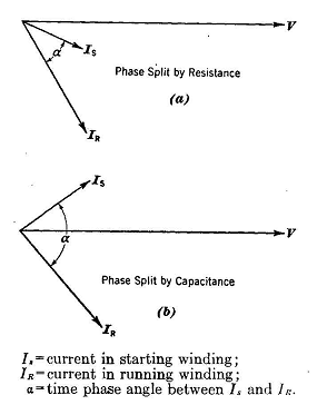
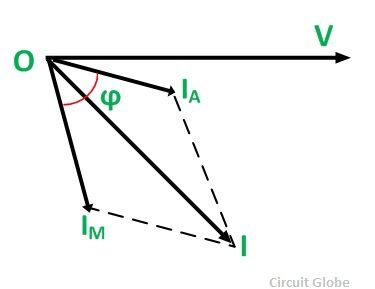
Split phase motor diagram. The phasor diagram of the Split Phase Induction Motor is shown below: The current in the main winding (I M) lags behind the supply voltage V almost by the 90-degree angle. The current in the auxiliary winding I A is approximately in phase with the line voltage. Thus, there exists a time difference between the currents of the two windings. The Split Phase Induction Motor is shown in figure 1. This motor is also known as Resistance-start motor. Contents show Fig. 1 Split Phase Induction Motor R m = main winding resistance X m = main winding inductive reactance R a = series resistor connected in the auxiliary winding X a = auxiliary winding inductive reactance The split-phase induction motor diagram is portrayed as below: Working of Split Phase Induction Motor Because of the non-uniform rotating field, the current across both the windings is not similar. So, starting torque is minimal which is almost 1.5 – 2 times more than initial running torque. Working of Split Phase Induction Motor The vector diagram for the split phase induction motor is shown in the Figure B. As the winding resistance of starting winding is high, the angle between voltage and current Is is small. Similarly the inductance of the running or main winding is high therefore the angle between Im and V is very large but less than 900.
Single-phase power distribution is used especially in rural areas, where the cost of a three-phase distribution network is high and motor loads are small and uncommon. Two phase power, meaning the simultaneous provision of sine wave and cosine wave electricity (that is, 90 degrees out of phase) is no longer widely used. Contactors and contactor assemblies. Power contactors for switching motors. SIRIUS 3RT contactors, 3-pole, up to 250 kW. SIRIUS 3RT12 and 3TF6 vacuum contactors. 3TG10 power relays/miniature contactors. Reversing contactor assemblies. Contactor assemblies for star-delta (wye-delta) starting. Contactors for special applications. Traffic behaves in a complex and nonlinear way, depending on the interactions of a large number of vehicles.Due to the individual reactions of human drivers, vehicles do not interact simply following the laws of mechanics, but rather display cluster formation and shock wave propagation, [citation needed] both forward and backward, depending on vehicle density. We look at power inverters used in cars and solar power to understand the basics of how they operate. We then cover electricity fundamentals, direct current, dc, ac, alternating current, single phase, three phase and split phase, electricity, pulse width modulation, variable speed drives, three phase rectification and more Circuit diagram
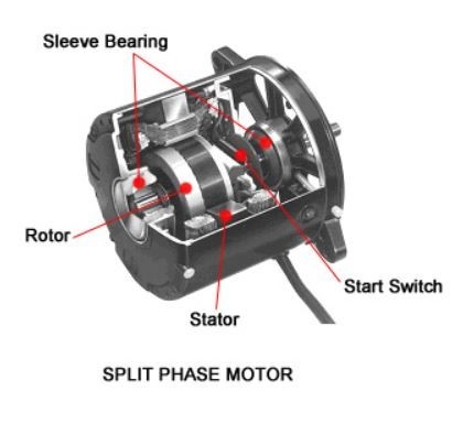
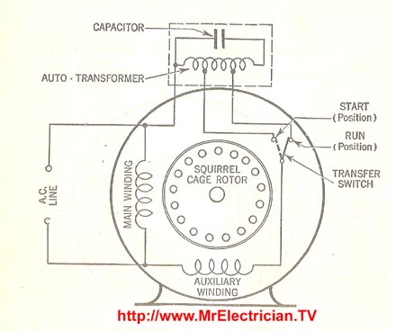
How To Connect A Single Phase Motor Diy Electrical Electric Motor Motor . Single Phase Capacitor Start Capacitor Run Motor Wiring Diagram Refrigerator Compressor Electrical Wiring Diagram Electrical Circuit Diagram . 455 Mfd 370 Or Vac Round Dual Run Capacitor Tp-cap-455440r Capacitor Electrical Schematic Symbols Electrical Jobs Fig-2: Ceiling fan capacitor connection diagram Well, a motor with either a start or run capacitor becomes an electrical capacitor that changes the current to multiple windings of a single-phase AC induction motor. This creates a magnetic torque. In other words, a fan will have a single-phase induction motor in it. The rotor (G) of the motor is of normal cage type. Fig. 1 (a) shows the motor schematically and Fig. 1 (b) shows its connection diagram. (a) (b) (c) Fig. 1 : (a) Schematic representation of a split-phase type single-phase induction motor, (b) Connection diagram, (c) Phasor diagram The following diagram shows the stator current complex space vector: a iS b c ia α2i c αib Figure 1: Stator current space vector and its component in (a,b,c) where (a,b,c) are the three phase system axes. This current space vector depicts the three phase sinusoidal system. It still needs to be transformed into a two time invariant co-ordinate ...

Types of Single Phase Induction Motors | Single Phase ...
English - 12. installing your dryer ElEctrIcal rEquIrEmEntS. The Wiring diagram is located on the plate below the control panel or frame back. • Improperly connecting the equipment grounding conductor can result in a risk of electric shock. Washing Machine Wiring Diagram And Schematics Washing Machine Motor Wiring Diagram.
The Split-Phase Induction Motor
Some commercially available double diodes have all four terminals available so the user can configure them for single-phase split supply use, half a bridge, or three-phase rectifier. For higher-power applications, a single discrete device is usually used for each of the six arms of the bridge.
What is a Split Phase Induction Motor? - its Applications ...
Contoh rumah minimalis atap miring yang pertama ini dibuat dengan konsep double roof yang memberikan tampilan dua bagian bangunan terpisah. 15 Model Teras Rumah Atap Miring Minimalis Atap merupakan pelengkap pada sebuah rumah yang telah di buat dengan seindah mungkin selain itu juga dapat kita miliki kenyamanan yang cukup fantastic untuk melindungi bagian atas rumah kita Namun yang akan saya ...

Electrical Engineering World: AC Split-Phase Induction Motor
A permanent split capacitor (PSC) motor is a type of single-phase induction motor. The circuit diagram of a permanent split-phase motor is shown in the figure below. The permanent split-phase induction motor consists of a squirrel cage rotor and the stator has two windings, viz. starting or auxiliary winding and main or running winding.

Canal Engineering, The Falkirk Wheel, Falkirk, Stirlingshire, Scotland.
Types Of Single Phase Induction Motors Split Capacitor Start Run Electrical4u ... equivalent circuit of a single phase capacitor start induction motor scientific diagram capacitor run single phase induction motor scientific diagram. Whats people lookup in this blog: ...
Capacitor Start 220v Single Phase Motor Wiring Diagram ...
Motor Control, Part 4: Understanding Field-Oriented Control. Field-oriented control (FOC) is a technique used to control various motor types, including permanent magnet synchronous machines (PMSMs). FOC makes use of Clarke and Park transforms that convert the three-phase sinusoidal currents into the direct and quadrature currents. You'll ...

Fangruida-Space R & D and manufacturing of new high-speed heavy-duty twin-engine rocket design.
24V - 6000W - 120V/240V Split Phase Camper Solar Wiring Diagram This diagram is for users requiring extensive power demands through 120V/240V split phase at up to 3000w per leg. This diagram also shows how to wire multiple solar arrays through multiple charge controllers into the Lynx Distributor.

Fangruida//"TERE"Frontier Rockets design cutting-edge technology --- overweight high-speed rocket
Phasor Diagram. The split phase induction motor phasor diagram is shown below. The flow of current within the IM (main winding) can be lagged after the voltage supply approximately through the 90 degrees angle. Here, IA is the flow of current within the auxiliary winding can be around in phase through the line voltage.

Help Wiring DPDT Switch to Reverse a 115v Split Phase ...
There are currently 248 Photo Index submissions for this manufacturer. Filter results by Machine Type: All Machine Types Band Saw Drill Press Grinder, Bench Hacksaw, Power Jig or Scroll Saw Jointer Lathe, Metal Lathe, Wood Motor Other Sander Shaper, Wood Table Saw. Show Thumbnail Images. You can sort the below table by clicking on the table ...

ElectricalForGas- Split Phase Motors - YouTube
Single Phase 120V/230V Distribution and Panel Board Wiring in Home. Single Phase wiring installation is the most common wiring in residential buildings. In Single Phase supply (230V in UK, EU and 120V & 240V in the US & Canada), there are two (one is Line (aka Phase, Hot or Live) and the other one is Neutral) incoming cables from the utility poles to the kWh energy meter and then directly ...

Canal Engineering, The Falkirk Wheel, Falkirk, Stirlingshire, Scotland.
This motor full-load amperage (FLA) calculator allows you to calculate the full-load current of the AC electric motor GoodCalculators.com A collection of really good online calculators for use in every day domestic and commercial use!

Split phase induction motor
45 diagram motor 1 phase. It includes instructions and diagrams for various types of wiring methods and other items like lights, home windows, etc. Single phase submersible motor starter wiring diagram pdf. Single phase three phase wiring diagrams 1 phase 3 phase wring the star delta y d 3 phase motor starting method by automatic star delta ...

33 Dayton Capacitor Start Motor Wiring Diagram - Wiring ...
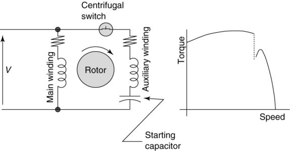
Another common type of single-phase induction motor is the Permanent Split Capacitor (PSC) motor. This motor uses an auxiliary winding which is physically offset from the main winding. This winding connected to the motor terminals via a capacitor, as shown in Figure 3. The auxiliary winding produces a weak field that creates the staring torque.

DAYTON 1/2 HP General Purpose Motor,Split-Phase,1725 ...
Split phase motor diagram is shown in the figure. I Run is the current in the main winding and I Start is the current in the starting winding. The angle between the two currents is φ as shown in the figure. Now the torque produced is such that it gives circular movement to the rotor.

Single Phase Capacitor Start Capacitor Run Motor Wiring ...
We look at power inverters used in cars and solar power to understand the basics of how they operate. We then cover electricity fundamentals, direct current, dc, ac, alternating current, single phase, three phase and split phase, electricity, pulse width modulation, variable speed drives, three phase rectification and more 3D 2D circuit diagram ...

Wiring Issues (with pictures)
Wiring a Split Phase Motor for Forward & Reverse. Hello - I spent some time looking at various posts on the forums for info on wiring a Split Phase Resistance Start Motor for forward and reverse, but haven't had much luck. Scott35 had posted some Schematics For: 1 Split Phase Motors - Series 1 years back that were helpful ( https://www ...

SPLIT PHASE MOTORS BASIC INFORMATION AND TUTORIALS ...
Maximize performance of 3-phase brushless motor and permanent magnet synchronous motors PMSM with our portfolio of BLDC motor drivers. And when viewing the figure below its easy to see why. The L6235 is a highly integrated mixed-signal power IC that allows to easily design a complete motor control system for BLDC motor.
Types of Single Phase Induction Motors | Single Phase ...
Blogs 04 November 2018 Seasonal Blog: Enter the autumn Read more. Blogs 31 October 2018 Three phase changes: the driving power behind a cooling machine Read more. Blogs 03 October 2018 The art of perfection: HVAC on a superyacht Read more. Blogs 17 September 2018 A closer look at the concept of temperature Read more.

Construction of a Motor - EEE COMMUNITY
Electric Motor Diagrams
.png)
Split Phase Induction Motor - Operation and ...

grey concrete house

body of water near mountain during daytime

The Falkirk Wheel, Connecting The Forth & Clyde Canal With The Union Canal, Falkirk, Stirlingshire, Scotland.
Circuit diagram of Permanent-Split Capacitor Motors ...
What is a Split Phase Induction Motor? - its Applications ...

Single Phase AC Induction Motors Instrumentation Tools

KBREEE: Split Phase Induction Motor
Types of Single Phase Induction Motors | Single Phase ...
Dayton Split Phase Motor Wiring Diagram - Wiring Diagram
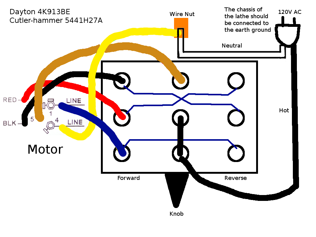
Getting Reverse to Work on a 120V Split-Phase Motor · Not ...

Split Phase Motor and Capacitor Start Induction Run Motor ...

Split Phase Motor and Capacitor Start Induction Run Motor ...

Fangruida/rocket tech

fangruida/Rocket Technology - Mars first pusher, heavy rockets and rocket overweight

DAYTON 1/2, 1/4 HP General Purpose Motor,Split-Phase,1725 ...

Single phase inductive motor - ECN Electrical Forums

Fangruida-rocket and space

green palm tree under white clouds during daytime
Types of Single Phase Induction Motors | Single Phase ...
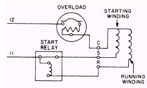
Single-Phase Hermetic Motors

aerial view of city buildings near body of water during daytime


Comments
Post a Comment