42 fire pump diagram
JPCV and PMCVE Drawings. Dimensionals. 10605 - JPCV: NEMA 2, Variable Speed Jockey Pump Controller. 24180 - PMCVE: NEMA 2,12 Variable Speed Pressure Mainenance Controller. External Wiring. 10604 - JPCV: Three Phase Variable Speed Jockey Pump Controller. Annual pump testing provides the necessary data to determine continued fire pump capability. The Pump Body. The pump body is the part of the fire pump that controls and directs the flow of water from the inlet side through to the discharge. Within the pump body are three main parts: the intake section, the volute section, and the discharge section.
B = Jockey Pump Sensing Line C = Fire Pump Controller D = Jockey Pump Controller C D A B January 2009 From Supply To System F E FIRE PUMPS ΠSENSING LINES Most commonly the pump controller is connected to the fire protection system by means of piping know as a sensing or pilot line. Each pump, including the jockey pump, shall have its own ...
Fire pump diagram
Fuse box diagram (fuse layout), location and assignment of fuses and relays Ford Fusion (2013, 2014, 2015, 2016, 2017, 2018). The heart of the pump/tanker is the impeller water pump. On this particular fire engine, the pump is located just behind the jumpseat area, where the firefighters sit. An impeller is a rotor-like device that has curved blades. Driven by its own diesel engine, the impeller spins inside the pump at a high rate. When water comes into the pump, it ... 19 Moreover Fire Truck Waterous Pump Pipe Diagram Photos is among the most images we found on the web from reliable sources. We attempt to discuss this fire truck waterous pump pipe diagram image in this article because according to info from Google engine, It is one of many top rated searches key word on google. And. Since our beginnings in ...
Fire pump diagram. Fire Pump Diagram. Here are a number of highest rated Fire Pump Diagram pictures upon internet. We identified it from obedient source. Its submitted by running in the best field. We take this nice of Fire Pump Diagram graphic could possibly be the most trending topic past we allowance it in google improvement or facebook. Fire pump is a part of a fire sprinkler system's water supply and powered by electric, diesel or steam. The pump intake is either connected to the public und... Listed indicating valve is installed on the fire protection system side of the pump. See diagram. Check valve is provided between the discharge valve and the pump. See diagram. No valves are installed in the relief valve piping A properly sized relief valve has been provided if pump is diesel driven or if churn pressure can Here's a 3-phase example. A 25-hp, 208V 3-phase fire pump motor is 175 ft from the service. The fire pump motor controller is 150 ft from the service. What size conductor must you install to the fire pump motor controller? Terminals are rated 75ºC. The answer: 3 AWG THHN. See Figure 695-2 un695-02 695-07 01.cdr
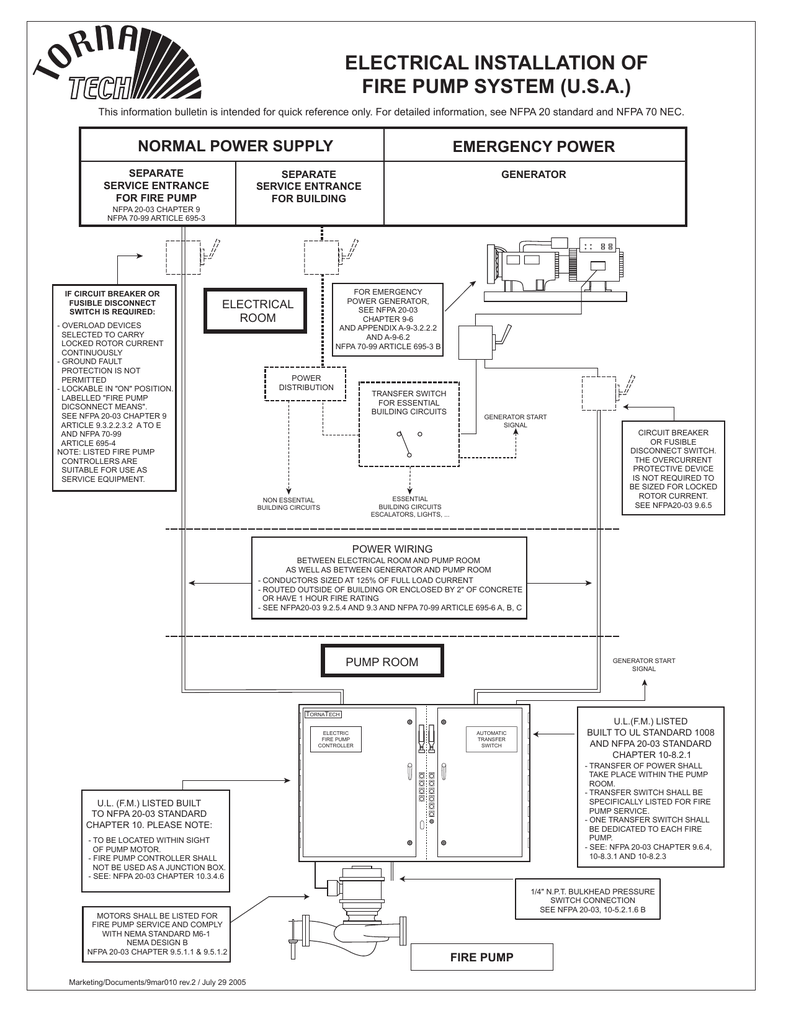
Designing Electrical Systems for Fire Pumps Since fire pumps are considered life safety equipment, they must be reliable. When designing or installing electrical power supplies for fire pumps and their accessories, you must apply special rules as listed in (NFPA 70), the National Electrical Code (NEC), and the Standard for Centrifugal Fire Pumps (CFP) NFPA 20. Centrifugal Fire Pump Principles of Operation, Inspection Tests and Troubleshooting Guide. F-1031, Section 1000 Revised: 11/21/96 Page 1 of 7 Principles of Operation The two main parts of centrifugal pumps are the impeller(s) and volute(s). The impeller is powered to rotate within the volute, creating centrifugal force which hurls This basic diagram was designed to help you understand the functionalty of a fire engine's pump and plumbing. Every fire engine's plumbing is build differently. Keep in mind that your fire engine's pump and plumbing will have a different configuration and may not be equiped with all the valves listed. 1. Fire Pump, 2. Auxiliary Pump, and 3. Ultra-High Pressure (UHP) Pump. In Canada, ULC S515 Standard for Automobile Fire Fighting Apparatus is the accepted standard to reference. Overview Modern fire apparatus pump systems are comprised of many components utilized to move and control water from a source.
Fire Pump Package systems are custom built to the requirements provided by the purchaser. The AC Fire Pump Package is a complete fire protec-tion system. Packaged Fire Pump Systems are designed in accordance with NFPA 20. Packages are factory hydrotested to internal quality standards and NFPA 20 requirements. PURPOSE OF MANUAL The Dakota fire pit is a tactical fire used by the United States military as the flame produces a low light signature, reduced smoke, and is easier to ignite under strong wind conditions. [2] This style of fire pit is said to get its name from the Dakota people , who used it while hunting Bison herds on the Great Plains during the colonial era ... Every fire pump installation needs to be provided with a testing means to ensure proper operation.At a minimum, arrangements must be provided to evaluate the pump at its rated condition as well as at its overload (150% of its rated capacity) condition. The means of testing must allow for the flow and discharge of significant quantities of water. Jan 05, 2022 · Sump pump is widely used to remove accumulated water from a sump pit or other location. Vacuum pump is applied to improve the efficiency of steam heating systems in many ways. The most important consideration is the rapid and efficient removal. Screw pump is the Archimedes screw pump that is still used in irrigation and agricultural applications.
Fire pump Diagram Compressed air foam system Waterous ...
CM/CS/CX Series Fire Pumps CR Series Fire Pumps HL Series Fire Pumps. Due to the larger file size, your download may take longer than preferred depending on device. We appreciate your patience. Questions on download application? Contact info@waterousco.com. 125 Hardman Ave S. South St Paul, MN 55075 | (+1) 651-450-5000
![[DIAGRAM] Wiring Diagram Jockey Pump FULL Version HD ...](https://d2t1xqejof9utc.cloudfront.net/screenshots/pics/0db6e8a6582f506507860452215955b0/large.jpg)
[DIAGRAM] Wiring Diagram Jockey Pump FULL Version HD ...
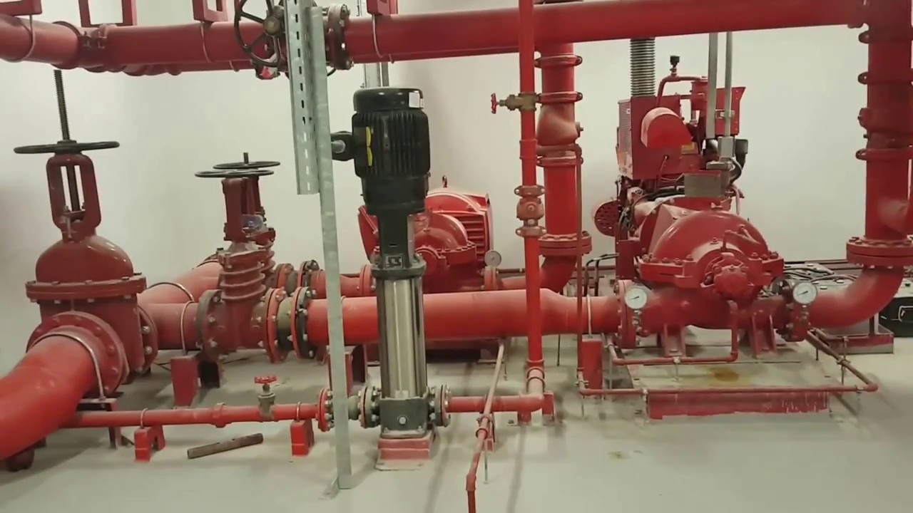
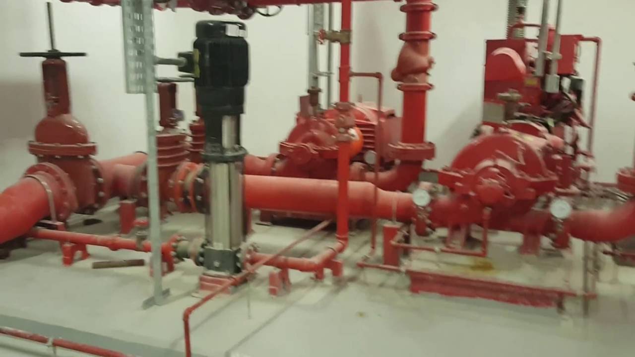
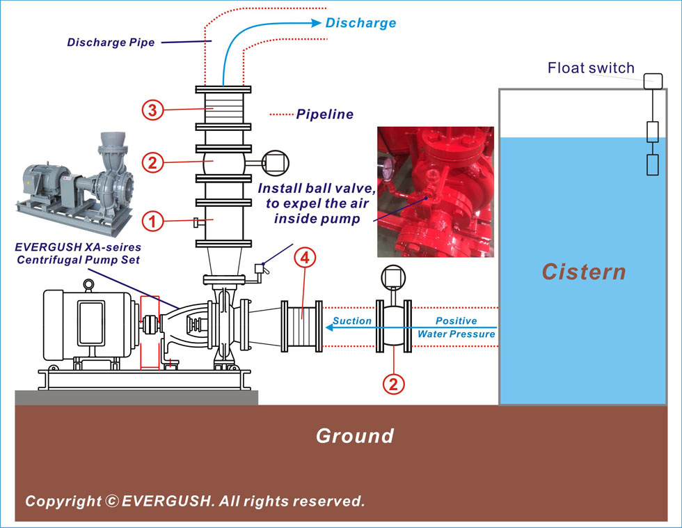
• If the fire pump are electric driven fire pumps, power supply need to be sustained or at least one fire pump need to be diesel engine fire pump. • Jokey pump is used to solve the issue of small pressure drops in the fire installation before the main fire pumps are activated; its flow rate must be min. 1/100 of the flow rate of the main ...

Fire Hydrant Systems - All Pumps Sales & Service - Leading ...
The main pump, often a centrifugal pump, is powered and installed at ground level. Its discharge is split, with the greater part of the flow leaving the system, while a portion of the flow is returned to the jet pump installed below ground in the well. This recirculated part of the pumped fluid is used to power the jet.

Elektische Ausrüstung—- Electrical installation
DIAGRAM GERAND GPM METER - VENTURI PACKAGE "B" - Butterfly Throttle Valve Air Vent Min. Straight Pipe Diameters same line size as Venturi Flow Flow (2) (5) FIRE PUMP "A" OSY Valve To System Optional to Pump Inlet Supply from City Main or Reservoir TO RESERVOIR OR WASTE OSY or Indicating Butterfly Bypass Valve

Engineer: Fire Pump Design Calculate (à¸à¸²à¸£à¸„ำนวณà¹à¸¥à¸°à¸à¸²à¸£à¸à¸à¸à¹à¸šà¸š ...
A fire pump is a device that provides the required water flow and pressure for a fire protection system. The fire pump unit itself consists of a pump, a drive, a driver coupling connecting the two, and a base plate. Fire pumps are normally purchased as a complete package that includes the following: Pump accessories (electric drive): Including ...

Fire Hydrant Systems - All Pumps Sales & Service - Leading ...
Fuse box diagram (fuse layout), location and assignment of fuses and relays Chevrolet Silverado and GMC Sierra 1500, 2500, 3500 (2003-2006).

29 Fire Pump Installation Diagram - Wiring Database 2020
FIRE PUMPS Rev. 1 Patterson Pump Company A GORMAN-RUPP COMPANY Post Office Box 790 Toccoa, GA 30577 Telephone: 706-886-2101 FAX: 706-886-0023 . TABLE OF CONTENTS SECTION 1 GENERAL INFORMATION AND DESCRIPTION PAGE

Fire Pump Schematic Diagram | Printable Worksheets and ...
Fire Apparatus Pump Operations, Mechanics, and Components Plain Water Operations Centrifugal Pumps Fire apparatus pumps use centrifugal force to deliver water to the fireground. Centrifugal force is an outward force associated with rotation. The rotation in a fire apparatus pump is powered

Maidstone ROYAL OBSERVER CORPS,Group HQ 57 London Road, Maidstone.
Figure 3: A general fire pump room schematic layout diagram is shown. Courtesy: WSP USA. Sizing a fire pump. A fire pump is designed to handle the most demanding fire sprinkler system. In a typical building like a high-rise office, there is the sprinkler demand on each floor, along with the standpipe. Other types of buildings may have a foam ...
Fire Pump Design Calculate Appilcation For Andriod - YouTube
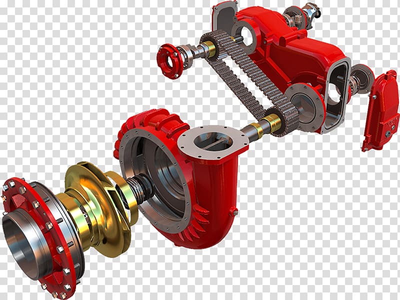
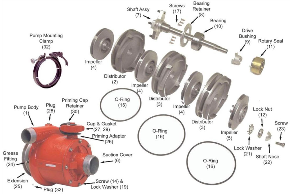
The "centrifugal pump", a critical component of the fire truck, is probably one of the most misunderstood components. A fire pumps is made up of three major parts: the speed increaser/pump transmission, the impeller shaft assembly, and the pump body. All play very important roles in the flow of water through the pump and into the discharge hose ...
Pump room in AutoCAD | CAD download (191.15 KB) | Bibliocad
Fire Pump Wiring Diagram. Find this Pin and more on My Saves by Dilchansada. The Custom Fire Department Keepsake Box includes your custom fire department artwork on the lid top, our standard fireman flames fire department front and a plain tray. Additional options are listed below. Handcrafted in the USA.

Doubt thou the stars are fire, Doubt that the sun doth move. Doubt truth to be a liar, But never doubt I love. -William Shakespeare
AC Fire Pump offers a range of vertical in-line pumps. The 1580 Series fire pumps are designed to provide water to stand pipe, sprinkler, chemical mitigation and hydrant systems for fire suppression in industrial and commercial facilities. The vertical design requires 30% less space than a traditional horizontal design.
fire pumps installation details - YouTube
with CFP, six (6) months from CFP shipment date), the diesel fire pump drivers, manufactured and sold by CFP, shall be free from defects in material and workmanship when used and serviced in accordance with the Operations and Maintenance Manual for the applicable Cummins Fire Pump engine model (the "Exclusive Warranty").

Fire Engine Pump and Plumbing Diagram
We recommend that a licensed contractor install all new systems and replace existing pumps and motors. Failure to install in compliance with local and national codes and manufacturers recommendations may result in electrical shock, fire hazard, unsatisfactory performance, and equipment failure.

Fire Pump Room Diagram - Diagram Media
If a transfer switch "approved for fire pump service" in accordance with Rule 32-208(1)(c)of the CE Code does not meet provisions of the current edition of the NFPA 20 (i.e.,integral overcurrent protection is bypassed in the fire pump controller/fire pump transferswitch arrangements, as shown in diagram 1), then current provision of Rule 32 ...

Fire Pump Piping Diagram Beautiful Nih Standard Cad ...
Waterous Fire Pump Diagram. 16.10.2018. 16.10.2018. 6 Comments. on Waterous Fire Pump Diagram. Warranty information contains the Conditional Warranty for Waterous Pumps. •. Instructions ous fire pump, transmission or power take−off. "Printed" service parts lists show exploded diagrams of a particular assembly along with part.

Barbados Screwdock
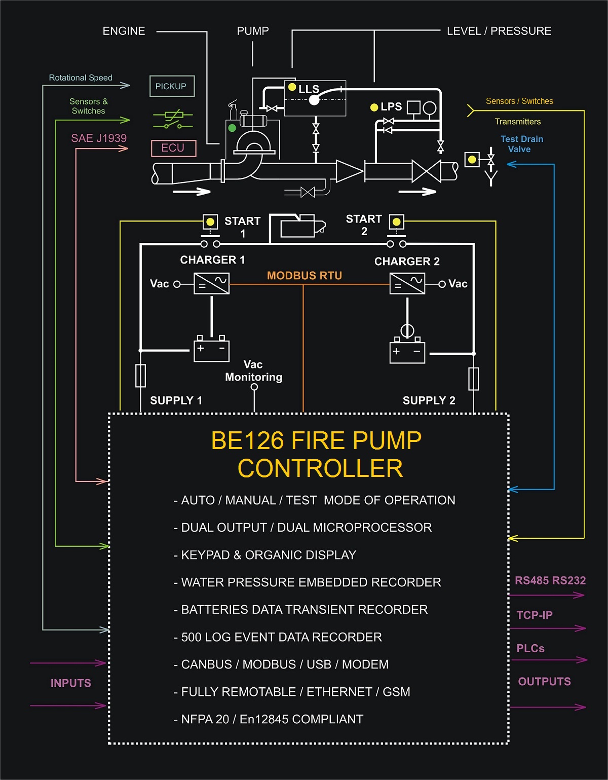
FIRE PUMP CONTROLLER WIRING DIAGRAM: DIGITAL INPUTS. DIGITAL INPUTS Connector JF (10 Poles) JF-1. MCB1 FAILURE. This input detects a failure of the battery charger 1. You can connect the output alarm relay of the battery charger '1'. The alarm triggers when you connect this input to the battery minus.
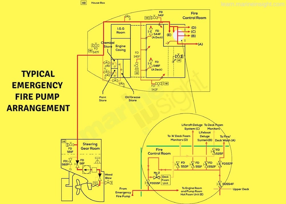
A Guide to Fire Pumps on Ship
A pressure relief valve controls the pump pressure and is designed to return the full pump capacity to the tank on unit. Schematic diagram and main components for SEM-SAFE ® high-pressure water mist system. The benefits of SEM-SAFE ® high-pressure water mist system Quick fire fighting
Fire Pump Installation Diagram - Drivenhelios
19 Moreover Fire Truck Waterous Pump Pipe Diagram Photos is among the most images we found on the web from reliable sources. We attempt to discuss this fire truck waterous pump pipe diagram image in this article because according to info from Google engine, It is one of many top rated searches key word on google. And. Since our beginnings in ...

Maidstone ROYAL OBSERVER CORPS,Group HQ 57 London Road, Maidstone.
The heart of the pump/tanker is the impeller water pump. On this particular fire engine, the pump is located just behind the jumpseat area, where the firefighters sit. An impeller is a rotor-like device that has curved blades. Driven by its own diesel engine, the impeller spins inside the pump at a high rate. When water comes into the pump, it ...
Mercedes Textiles - WICK® FSP4200 4-Stage Pump Parts ...
Fuse box diagram (fuse layout), location and assignment of fuses and relays Ford Fusion (2013, 2014, 2015, 2016, 2017, 2018).

Eiffel Tower...Tightrope walking

Fire Pump And Jockey Pump Wiring Diagram - How Flex

Waterous Fire Pump Diagram
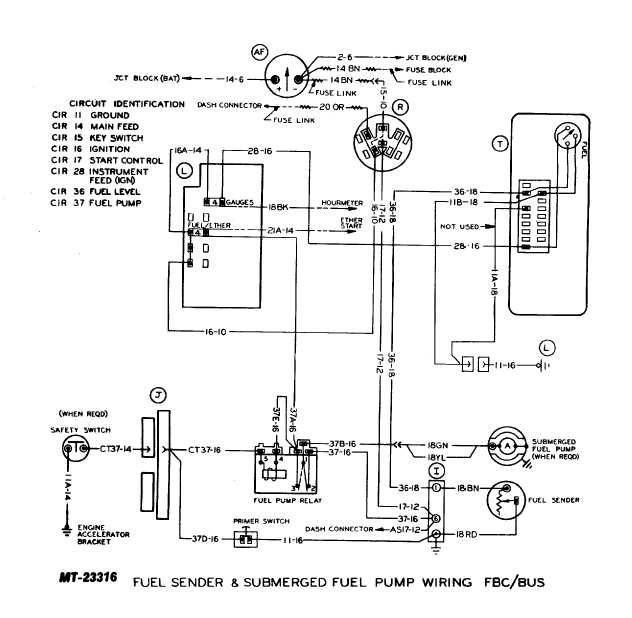
Engine Wiring Diagram For A 3412 Fire Pump Engine

Fire Pump Controller Wiring Diagram | Free Wiring Diagram
![[SO_4659] Fire Engine Centrifugal Pump Cutaway Diagram ...](https://static-cdn.imageservice.cloud/5936453/the-story-of-pumps-3.jpg)
[SO_4659] Fire Engine Centrifugal Pump Cutaway Diagram ...

Фото Ивана МиÑко и Олега Ðовицкого на Международной коÑмичеÑкой Ñтанции. Photo by Ivan Misko and Oleg Novitskiy at the International Space Station.

Fire Pump And Jockey Pump Wiring Diagram - How Flex

PPT - Fire Pump Theory PowerPoint Presentation - ID:1159597

Fire Pump Package & Skids | Mechanical Equipment Company

Ministry Of Defence, Vulcan Naval Reactor Test Establishment, Caithness, Highlands, Scotland.

Waterous Fire Pump Diagram

The chimney

Fiery silhouette

Jet D'eau, Tallest Water Fountain In The World, Lake Geneva, Geneva, Swiss Confederation.
Fire Pump Transfer Switch Wiring Diagram - Wiring Diagram ...
![[DIAGRAM] Wiring Diagram Panel Pompa Hydrant FULL Version ...](https://allpumps.com.au/wp-content/uploads/2018/04/diesel-fire-hydrant-drawing-side.png)
[DIAGRAM] Wiring Diagram Panel Pompa Hydrant FULL Version ...

WATEROUS - Discharge Relief Valve - YouTube
EN 12845 fire fighting - Automatismes pour groupes ...

Wiring Diagram Panel Pompa Hydrant

Waterous Fire Pump Diagram


Comments
Post a Comment