41 autometer fuel level gauge wiring diagram
To fuel level sender. PURPLE: Used for triggering (grounding) relay coil when low set point of the gauge is triggered. PROGRAMMING CALIBRATION FOR VARIOUS ... Wiring diagram for auto meter new wiring diagram auto gauge a newbie s overview of circuit diagrams. Toll free tech support. Pin On Gauges . Higginbotham fuel gauge wiring diagram rate fuel gauge wiring autometer gauge wiring diagram additionally wiring diagram provides you with enough time frame by which the assignments are to be accomplished.
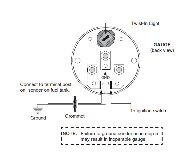
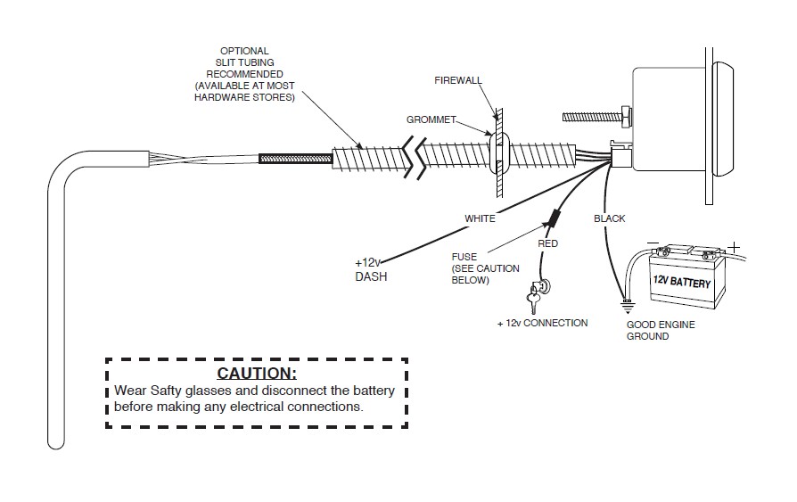
Fuel Level. 1. Gauge connects to fuel sender on fuel tank. Existing wires may be used, or route proper length of 18 gage, wire from fuel tank to gauge. If a new hole is drilled in the firewall a grommet is recommended. Connect one end to terminal post on fuel level sender and the opposite end to the sender (S) terminal spade on back of gauge. 2.

Autometer fuel level gauge wiring diagram
Index of /media/manual Air Fuel Ratio Gauge. Autometer gauges faulty after wiring fuel ratio monitor installation auto meter 3810 user manual 2 pages how to install oil pressure 3363 sensor air gauge 1 16 0 100 psi with racepak usm wrangler tj on your jeep wire harness for elite 5 ultra replacement full start kart plans cobalt wideband 5763 electric sweep cruzpro rp60 nmea 0183 remote data 2198 universal lite 8 ... The most common cause of a fuel level gauge of this type to read only past full is if the “S” terminal of the gauge is somewhere shorted to chassis ground or of the sender is internally shorted to ground. A quick and easy way to check the gauge is to remove the sender wire from the back ...
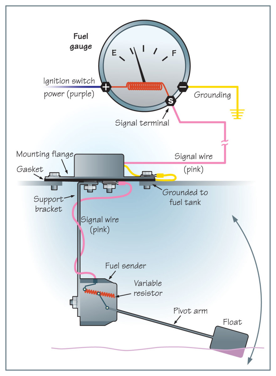
Autometer fuel level gauge wiring diagram. The AutoMeter Digital Stepper Motor Fuel Level Gauge drastically simplifies the process with its easily configurable resistance range. With 7 common configurations stored in memory from the factory, the vast majority of all applications are covered. In the instance your fuel level sender is not included in these preconfigured ranges, an ... Existing wires may be used, or route the purple sender wire to the fuel tank. (The stock fuel level gauge, if equipped, must be disconnected.). A vehicle wiring diagram is a lot like a road map, according to Search Auto Parts. Wiring diagrams are laid out similar to a road map because the diagrams show how each major electrical system, individual circuit and sub-system connects, th... (see diagram for details). 6. Connect purple wire to fuel level sender, making sure that the sender is grounded. 7. Reconnect negative (-) battery cable.
I just got done installing a new fuel level sending unit in my 86 gt mustang and purchased a new autometer fuel gauge to go with it. But as far as wiring is concerned, I don't have a clue. Someone had mentioned that I could t-tap a wire off of the stereo power wire (which I did). But I can't seem to get the damn thing to work. Wiring diagrams. 2 - 9. trim gauge, fuel gauge, fresh water gauge for level-type sensor. TU 1 . Only connect cables according to the electrical wiring diagram . VDO has tried to answer most of your questions regarding Installation and Trouble Note: These Instructions are for VDO Gauges and Accessories only. INSTRUCTIONS FOR THE INSTALLATION OF ... 5. Connect the other end of the wire to the Speedometer. Fuel Level Gauge 1. Attach the ground ring connector and positive wire using a ring connector to the gauge. 2. Pick a color wire for the sending unit wire and connect it to the gauge using a ring connector. 3. Equus tachometer wiring diagram further how install tach also r1 tach wiring diagram moreover rpm circuit diagrams further autometer fuel level gauge wiring diagram as well as autometer fuel gauge wiring diagram as well as honda shadow wiring diagram as well as honda bf50a tachometer wiring diagram furthermore autometer volt install along with ...
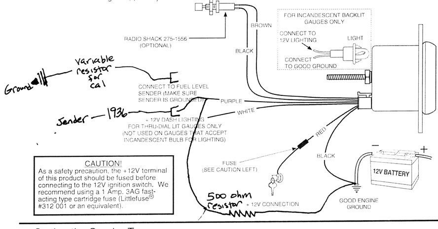
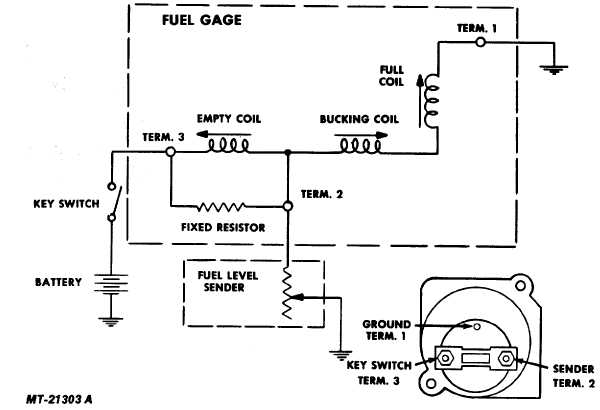
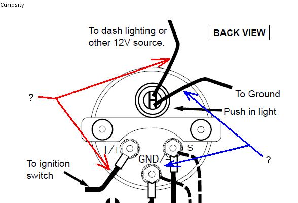
Autometer Phantom Fuel Gauge Wiring Diagram. By Admin | November 2, 2017. 0 Comment. Auto meter 4379 user manual 2 pages also for 8079 1 16 fuel pressure 0 100 psi stepper motor phantom air ratio gauge 5737 electric water temperature gauges interior accessories cajaalimentos com br 21 wide band monitor 3810 5910 8010 1109 narrowband lean rich ... Those autometer gauges never work just right even if you get them adjusted right. Vince and doc and cletis are all right, the sender needs to be matched to the gauge. There are about 5 or more ranges that those run in, 90-0 ohms, 0-90, 240-33, 73-10,10-180 all different resistance values for different gauge mfgs. Jan 19, 2020 · Autometer Fuel Level Gauge Wiring Diagram – wiring diagram is a simplified all right pictorial representation of an electrical circuit. It shows the components of the circuit as simplified shapes, and the capability and signal friends between the devices. 2. Using 18-ga. wire, connect the (G) terminal to a clean (rust/paint-free) Figure 4ground. 3. Using 18 gauge wire, connect the (I) terminal to a switched +12V source. 4. Using 18-gauge wire, connect the (S) sender terminal of the gauge to the fuel level sender. 5. Connect one the light wire to the dash lighting circuit or to a +12V switched ...
Autometer Gauge Wiring Diagram Short Sweep
Due to shipper delays and a high level of demand, your order may take longer to arrive

Autometer Gas Gauge Wiring Diagram - Search Best 4K Wallpapers
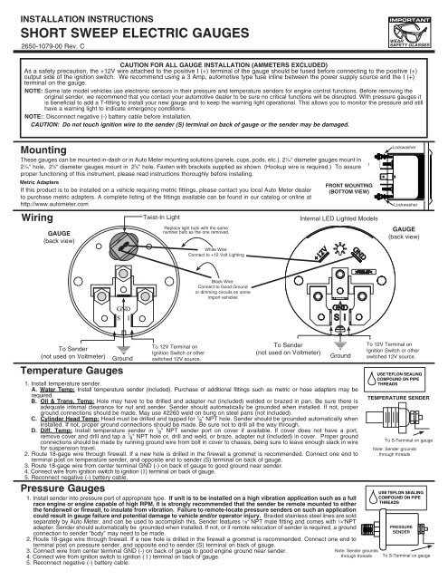
These gauges can be mounted in-dash or in Auto Meter mounting solutions (panels, cups, pods, etc.). ... 18 gage, wire from fuel tank to gauge.
Autometer Gas Gauge Wiring Diagram - Search Best 4K Wallpapers
I have a autometer 7114 autometer c2 programmable fuel level gauge purple goes to sending unit wire but i don't have wiring diagram for a 1997 f150 4.2 v6 i have 4 wires 1 large pink/blue, 1large black, 1yellow small,1 small black/orange, from factory unit ,purple to which one? i don't want pull gas tank.
VDO Performance Instruments
Autometer Gas Gauge Wiring Diagram. Auto meter 3810 user manual 2 pages also for 5910 8010 1109 installation instructions cobalt air fuel ratio gauge digital 79 17 all americanmuscle spridgetguru com tech index wiring diagram how to test and replace your sending unit sail magazine 21 16 quot monitor install direct fit dash panel 97 06 wrangler ...

29 Autometer Fuel Gauge Wiring Diagram - Free Wiring ...
Index of /media/manual
Aftermarket fuel gauge on stock tanks...? How to ...
Due to shipper delays and a high level of demand, your order may take longer to arrive
Wiring Diagram Info: 35 Autometer Fuel Gauge Wiring Diagram
SHORT SWEEP ELECTRIC FUEL LEVEL GAUGE 2650-1858-77 Wiring: Sending Unit Wiring: Gauge Mounting: Gauge to Sender Compatibility: Looking at the rear of the gauge, you will have 3 terminals labeled S, I, & GND. You may use 18g or 20g stranded wire for all fuel level gauge wiring. S = This connects to the sending unit in the fuel tank. **(See Sending Unit Wiring Section)
Fuel Gauge Wiring Diagram - Wiring Diagram
Fuel Level gauge Specifications MODeLS 2315, 2316, & 2320 NOTE: For the following installation THe gAS TANK MUST Be FULL! 1. Disconnect negative (-) battery cable. (Wear safety glasses) 2. Gauge uses vehicle’s stock sender in fuel tank. Existing wires may be used or route proper length of 18-gage, 2 conductor wire from fuel tank to gauge.
Autometer Voltmeter Wiring Diagram - Wiring Diagram
Auto Meter Products. 413 W Elm St. Sycamore, IL 60178. Toll Free Tech Support: 866.248.6357. Toll Free Customer Service: 866.248.6356. International: 815.895.8141
Wema Fuel Gauge Wiring Diagram
A home or vehicle is a maze of wiring and connections, making repairs and improvements a complex endeavor for some. Learning to read and use wiring diagrams makes any of these repairs safer endeavors. These simple visual representations all...
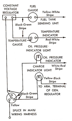
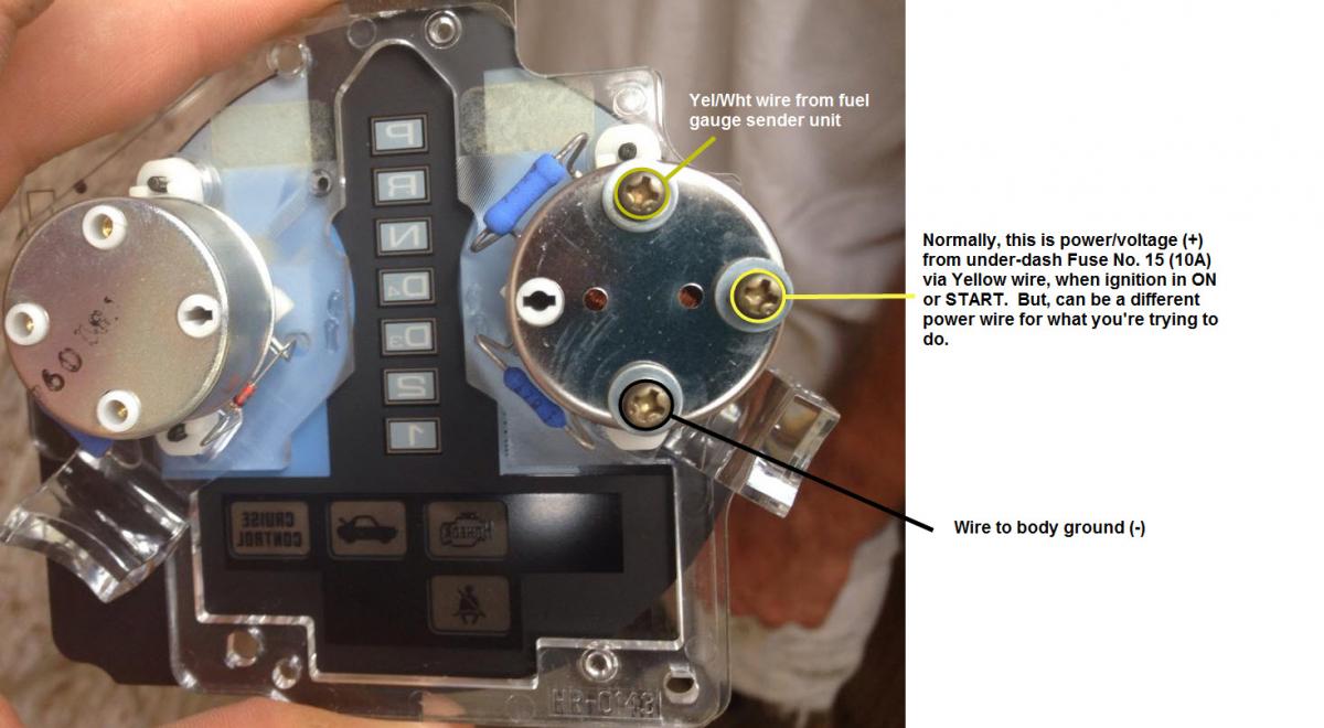
Dash Instrument Testing - Falcon Enterprises
Full sweep electric fuel level, Setting the sender type installation, Installation instructions • Read online or download PDF • Auto Meter 3810 User Manual.
Autometer Sport Comp Fuel Gauge Wiring Diagram | Soffast
Autometer Fuel Level Gauge Wiring Diagram Autogage Tach Wiring Wiring Diagram is one of the pictures that are related to the picture before in the collection gallery, uploaded by autocardesign.org.You can also look for some pictures that related to Wiring Diagram by scroll down to collection on below this picture. If you want to find the other picture or article about Autometer Fuel Level ...
How to Install Auto Meter Sport Comp II Transmission Temp ...
Fuel Level Gauges Autometer How They Work How To Install Tutorial Instructions Ohms Wiringhttp://www.jegs.com/vct/Auto+Meter/105/1010331-----...
How to Install Auto Meter Oil Pressure Gauge - Electrical ...
Due to shipper delays and a high level of demand, your order may take longer to arrive

Wiring Diagram Info: 22 Autometer Gauges Wiring Diagram
A wiring diagram is a simplified conventional photographic depiction of an electric circuit. Existing wires may be used or route the purple sender wire to the fuel tank. The stock fuel level gauge if equipped must be disconnected 5. Connect ground wire from ground post on gauge to suitable chassis ground. Gauge mounts in a 25 8 hole for 2 5 8 ...

Autometer Air Fuel Gauge Wiring Diagram - anchillante
Step 4. Connect the "S" wire to the fuel-sender signal wire you removed from the stock fuel gauge. This wire is fed directly to the post on the fuel-level sender in the fuel tank. Twist these two wires together and cover them with a layer of electrical tape. Use your test lamp to determine the fuse for the dashboard instrument lights.
Wema Fuel Gauge Wiring Diagram
Connect one end to terminal post on fuel level sender and the opposite end to the sender (S) terminal spade on back of gauge. 2. Connect ground wire from ground post on gauge to suitable chassis ground. 3. Connect wire from ignition switch to the positive I (+) terminal on the back of gauge. See figure right. 4. Reconnect negative (-) battery cable. 5.
Sn95 Gauge Wiring Diagram - Complete Wiring Schemas
Existing wires may be used, or route the purple sender wire to the fuel tank. (The stock fuel level gauge, if equipped, must be disconnected.).
Auto Meter 1398 Arctic White Air-Core In-Dash Tachometer ...
Existing wires may be used, or route proper length of 18 gauge, 2 conductor wire from fuel tank to gauge. Connect one end to terminal post on fuel level sender ...
Marine Fuel Gauge Wiring Diagram : Mack Truck Fuel Gauge ...
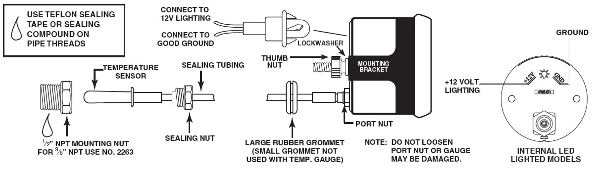
wiring instructions. Always disconnect battery ground before making any electrical connections. Parts of the Fuel Level Sender Unit to be Ad Fuel Level Sender Installation: Refer to the VDO catalog for matching fuel gauges. The unit can be adjusted to read accurately in tanks from 6" to 23" deep. Diagram B I. Measure the depth of your fuel tank.

Autometer Fuel Level Gauge Wiring Diagram
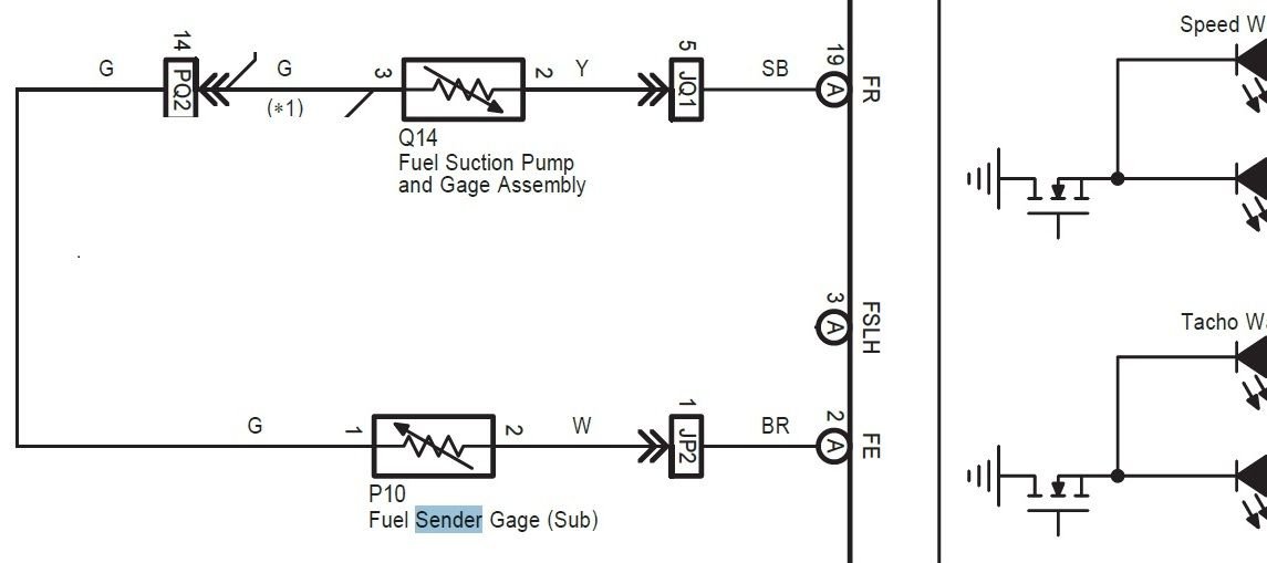
the reason is that the autometer gauge, an american product, is designed to compensate for "dumb" fuel sending units. our sender, a japanese product, already does this compensation, sending a nearly perfectly linear signal, very much indicative of the actual fuel level. our oem gauge is "dumb" in that the needle's indication is directly ...

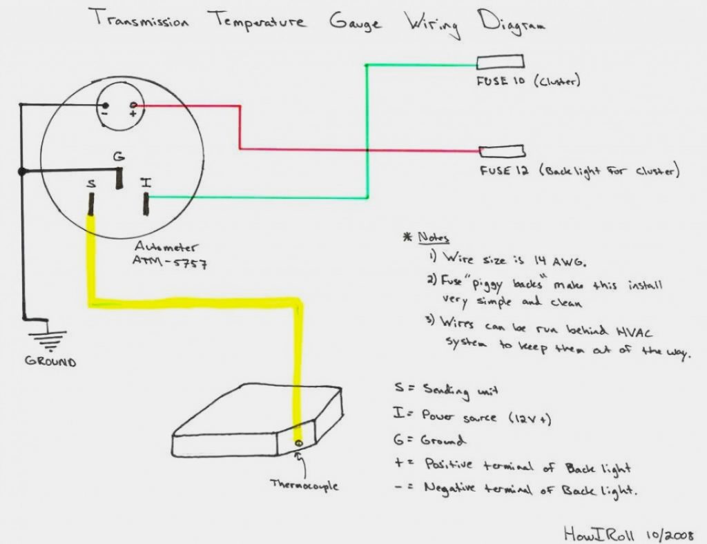
Autometer Trans Temp Gauge Wiring Diagram
Isspro pyrometer gauge wiring the hull truth boating and fishing forum weird electrical issues turbo sel register installation instructions for optional a relay controlled output caution autometer c2 pyro place tech egt exhaust gas temperature westach westberg diagram digital boost vac 2650 1236 00 manualzz work hours counter android 2 1 16 0 1600 f stepper motor sport… Read More »
Boat Fuel Gauge Wiring Diagram - 20 Fresh Boat Fuel Gauge ...
This is for an AutoMeter Fuel level gauge part 3514. 0 Ohms empty, 90 Ohms full for most GM vehicles from ´65 to present. ... If you ground the meter to the sender body and probe the terminal that the gauge wire attaches to you can then move the float by hand and watch the meter to see what it reads. Call Auto Meter, they have a service number ...
Autometer Temp Gauge Wiring Diagram - Hanenhuusholli
Use 20 AWG.Sep 19, · Updating To An Electrical Gauge Package Hotrod Hotlinerhhotrodhotline also Auto Meter Speedometer Wiring Diagram Schematic Electronic Rhselfitco further Auto Meter Tach Wiring Diagram On Hei Trusted Diagramsrhkroudco in addition Autometer Fuel Level Gauge Wiring Diagram Electrical Diagramsrhwiringforalltoday and Wiring ...

I have problem with 200 hp optimax 1yr old and only 34 hrs ...
Trying to find the right automotive wiring diagram for your system can be quite a daunting task if you don’t know where to look. Luckily, there are some places that may have just what you need. Here’s where to start. Before you search for a...

Auto Meter Tach Wiring Schematic | schematic and wiring ...
Autometer Fuel Level Gauge Wiring Diagram Wiring Diagram Online,autometer fuel level gauge wiring diagram complite Wiring Diagram

30 Autometer Fuel Gauge Wiring Diagram - Wiring Database 2020
Due to shipper delays and a high level of demand, your order may take longer to arrive
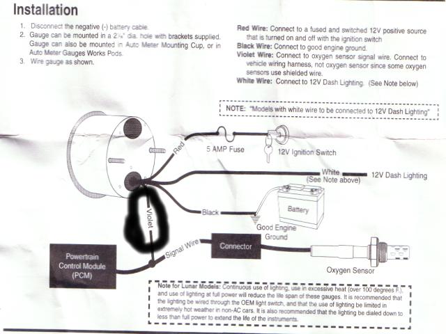
How to Install an Auto Meter Pro-Comp Ultra-Lite Fuel ...
4. Connect the purple sender wire to the fuel level sender. Existing wires may be used, or route the purple sender wire to the fuel tank. (The stock fuel level gauge, if equipped, must be disconnected.) 5. Connect the white wire to dash lighting or switchable 12v light source. 6. Connect one of the black wires to a good ground.
Autometer Gas Gauge Wiring Diagram - Search Best 4K Wallpapers
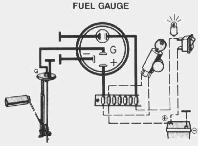
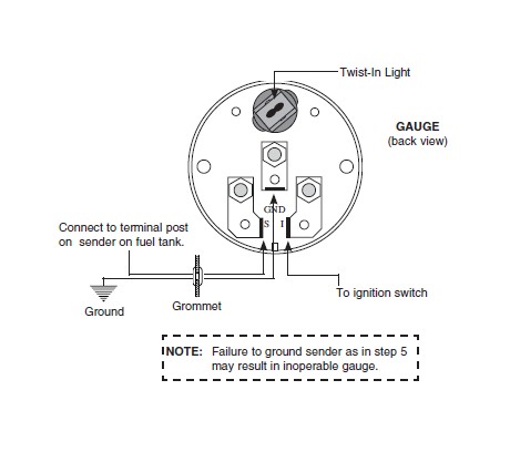
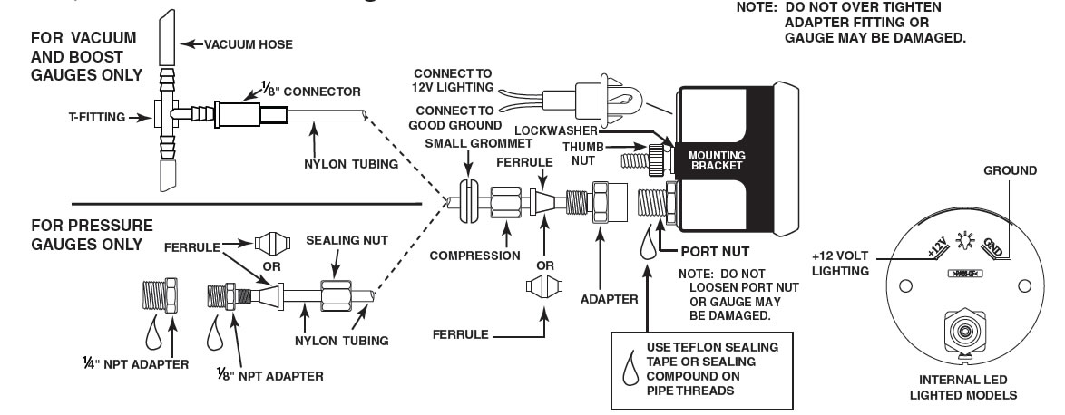
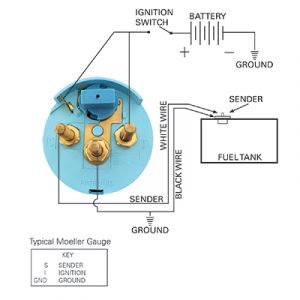
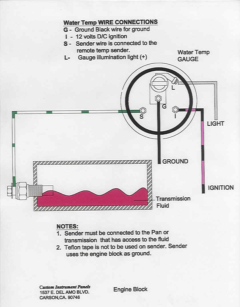
Fuel level. 1. Gauge connects to fuel sender on fuel tank. GAUGE (back view) Wiring Ground Note: Sender grounds through threads Black Wire: Connect to Good Ground or dimming circuits on some import vehicles GND S I Pressure Gauges Temperature Gauges TEMPERATURE SENDER USE TEFLON SEALING COMPOUND ON PIPE 1. Install temperature sender.
fuel level sender problems - ClubLexus - Lexus Forum ...
Nov 19, 2020 · Autometer Pro Comp Ultra Lite Wiring Diagram Fresh Auto Meter Wiring – Autometer Gauge Wiring Diagram. Wiring Diagram arrives with several easy to follow Wiring Diagram Guidelines. It’s intended to aid all the average person in developing a suitable method. These guidelines will be easy to understand and apply.

Autometer Air Fuel Gauge Wiring Diagram - anchillante
Trans Temp Gauge Installation: but an A-pillar gauge mount is available as a professional location to mount two gauges. diagramweb.net has a 2 & 3 gauge pod available Pictured below is a copy of the wiring diagram for the Autometer Transmission Temperature Gauge. STEP 4.
1979 Suzuki Gs550 Wiring Diagram With Fuel Gauge
The most common cause of a fuel level gauge of this type to read only past full is if the “S” terminal of the gauge is somewhere shorted to chassis ground or of the sender is internally shorted to ground. A quick and easy way to check the gauge is to remove the sender wire from the back ...
Fuel gauge wiring HELP - The Hull Truth - Boating and ...
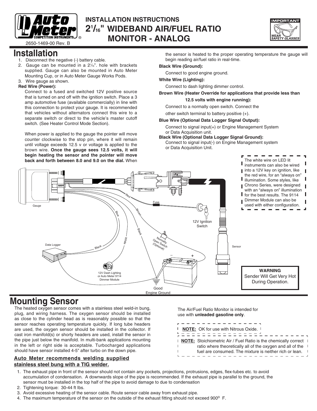
Air Fuel Ratio Gauge. Autometer gauges faulty after wiring fuel ratio monitor installation auto meter 3810 user manual 2 pages how to install oil pressure 3363 sensor air gauge 1 16 0 100 psi with racepak usm wrangler tj on your jeep wire harness for elite 5 ultra replacement full start kart plans cobalt wideband 5763 electric sweep cruzpro rp60 nmea 0183 remote data 2198 universal lite 8 ...
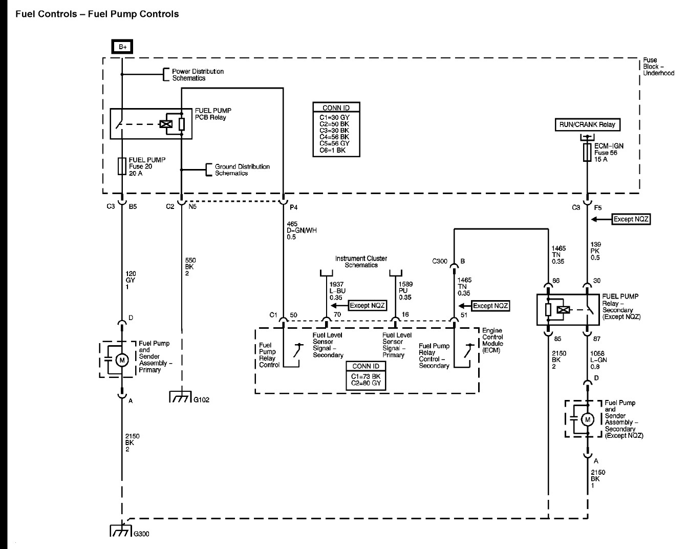
![!/[PDF] Gm Fuel Sending Unit Wiring Diagram](https://i.pinimg.com/originals/98/3d/7a/983d7a09f3be0ed82972dffc00ae7459.png)
!/[PDF] Gm Fuel Sending Unit Wiring Diagram
Index of /media/manual
![DOWNLOAD [DIAGRAM] Waste Oil Wiring Diagram Full Quality ...](https://rennlist.com/forums/attachments/944-turbo-and-turbo-s-forum/75591d1125497264-oil-temp-gauge-sender-wiring-vdo-gauge-install.jpg)
DOWNLOAD [DIAGRAM] Waste Oil Wiring Diagram Full Quality ...
Autometer Oil Pressure Gauge Wiring Shortcut? - General ...

Autometer Air Fuel Gauge Wiring Diagram - anchillante

Autometer Electric Fuel Pressure Gauge Wiring Diagram ...
Autometer Water Temp Gauge Wiring
How to Install an Auto Meter Pro-Comp Ultra-Lite Fuel ...

Sunpro Gauge Wiring Diagram - Complete Wiring Schemas


Comments
Post a Comment