40 engine oil flow diagram
Engine Control Module, EVAP Canister Purge Volume Control Solenoid Valve, Engine Coolant Bypass Valve Control Solenoid Valve, Fuel Heater and Water in Fuel Level Sensor, High Pressure Fuel Pump, Condenser, Ignition Coils, Exhaust Valve Timing Control Solenoid Valve, Intake Valve Timing Control Solenoid Valve, Fuel Injector Relay, High Pressure Fuel Pump … 5 7 Hemi Diagram. Here are a number of highest rated 5 7 Hemi Diagram pictures upon internet. We identified it from obedient source. Its submitted by doling out in the best field. We endure this kind of 5 7 Hemi Diagram graphic could possibly be the most trending topic subsequently we allocation it in google improvement or facebook.
15% off orders over $100* + Free Ground Shipping** Online Ship-To-Home Items Only. Use Code: DEALS4JAN

Engine oil flow diagram
6.0 Powerstroke Oil System Diagram. 1 on page 38 shows a simple oil flow schematic for the L diesel engine. In order for the fuel injectors to operate, a minimum of psi oil pressure is required. The oil is the life blood of the L diesel as the injectors are The oil is run through a low pressure oil pump which pushes oil to the oil filter at. In this short animation I briefly explain how the oil flows through an engine when its started after an oil change.#oil#engine#howitworks#GarageTech#circulat... There are several factors which contribute to the lower efficiency of the IDI engine (Monaghan, 1982): (i) combustion tends to continue until later in the expansion stroke: this is partly because injection usually starts later and partly because combustion takes longer in a pre-chamber engine; (ii) pumping losses are greater on account of the flow through the throat; (iii) heat …
Engine oil flow diagram. The lubrication system is pressure regulated, cooled, and full flow filtered. In addition to providing engine lubrication, it supplies oil to the high-pressure oil system to control fuel delivery in the fuel injectors. The following sequence describes lube oil flow through the major oil system components: 1. Oil pan (sump). 2. Oil pickup tube ... The oil goes through several different paths returning to the bottom - but only one path, under pressure, to do its job. Figure 1 shows a tube with a loose-weave metal screen at the bottom of the pan. The screen is attached to a pickup tube, which leads directly to the oil pump. Starting a new playslist called QuickFlix. These will be Totally Random videos designed to be quick and informative on whatever topic comes up. This topic ... Engine Diagram for 4-134 F-Head (Hurricane) Engine. Diagram Part #1. Part #: J8993146. Filter, Engine Oil $ 5.99. Fits: 1953-1968 CJ3B w/ 4-134 F-Head Engine 1966-1978 CJ5 w/ 3.8L Engine 1966-1975 CJ6 w/ 3.8L Engine 1976-1978 CJ7 w/ 3.8L Engine 1971-1982 CJ5 w/ 4.2L Engine
Joined Jun 6, 2001. ·. 5,551 Posts. #2 · May 21, 2008. number one will be one of the last to get oil on a 302. Oil flow....pump is a positive displacement pump, meaning that if it turns, it pumps. Oil flows from the pump to the filter. Out of the filter and to the main galley. Down the main galley. 11.11.201811.11.20181 Commentson Harley Evo Oil Flow Diagram Routing the oil lines from the oil tank to the engine is simple task. The design of the oil filter on the shovelhead uses one oil line, which feeds the oil back through the filter and into the oil tank. The evolution’s external filter requires two oil lines; one line feeds. Oil Pumps. Stock big-block Chevy oil pumps have been available in two configurations: standard volume or high volume. The difference is merely the length of the spur gears inside the pump housing; standard-volume gears are 1.135 inches long, and high-volume gears are 1.300 inches. Either design fits any standard big-block rear main cap. Sadly, there is no good solution for modifying the 216 engine for full flow (but we can add the Spin-On system anyway), but if you feel that 12% of the oil being filtered is as ridiculous as I do, instructions on how to modify your 1953-1962 235 or 1954-1957 261 engine can be found further down this page. In 1958, GM offered the 261 with full flow capability and every GM engine …
Jaguar-Engine-Oil-Flow-Diagram. It was the fourth new engine type in the history of the company. Hot spots may develop in the head. Jaguar X-Type Sedan And Estate (Wagon). Manual - Part 243 from www.zinref.ru. Lube pressure oil system schematic. The solution to is a bypass passage which allows coolant to flow around the engine and back to the ... Any body got a link to an oil flow diagram for a 4.0 ? I saw one somewhere but I can't find it now no matter where I look. ... Try using the search, I plugged in "oil flow chart for 4.0" and got this top of the list. ... Come join the discussion about performance, engine swaps, modifications, classifieds, troubleshooting, maintenance, and more! Engine oil flow schematic (Wanted) Jump to Latest Follow 1 - 7 of 7 Posts. motorheads5 · Premium Member. Joined Mar 1, 2010 · 831 Posts . Discussion Starter · #1 · Apr 1, 2010. I am looking for an Engine oil flow drawing/schematic of a new twin cam A motor including the oil tank ect. as in the streetglide platform. ... 2. Filter Relocation Kit . 1. With a sandwich plate you are basically putting a piece of metal with an input and output barb for the oil cooler, that is sandwiched between the block and the oil filter. This is an easy and great way to add the outputs you need when adding the oil cooler if you have the space to add a sandwich plate on the block.
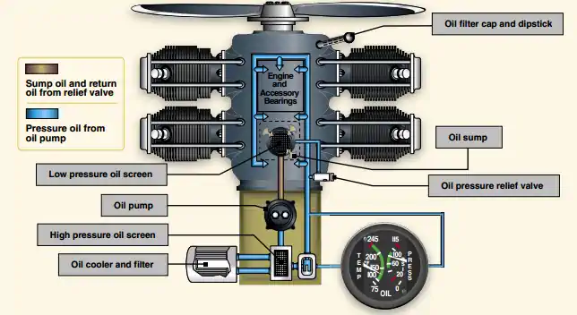
Aircraft Turbine Engine Dry Sump Variable Pressure ...
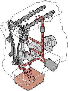
An automotive engine is a diverse collection of static and moving parts, ranging from the engine block to the crankshaft to cylinder heads, but without proper oil flow and control, none of those parts would be able to function properly.

Lube Oil System - an overview | ScienceDirect Topics
The oil is the life blood of the L diesel as the injectors are The oil is run through a low pressure oil pump which pushes oil to the oil filter at. 1 on page 38 shows a simple oil flow schematic for the L diesel engine.

What's generally on the other side of the oil filler cap ...
From what I understand, one valve lets oil flow bypass the cooler when the oil is super cold and flow resistance is high. The other valve bypasses the filter if the filter becomes plugged up. Old school chevys have a valve that does the same thing built into the filter adapter, while the 6.2/6.5 have them in the block.
EJ255 Engine Oil System Diagram - Subaru Legacy Forums
98 GMC 2500 hd sle 6.5td ext cab l box 4x4 auto 4.10 difs 268000 km. HOME REBUILD ENGINE at 268.000 km,currently 307.000 Removed CDR an installed PROVENT CRANK CASE OIL SEPERATOR/VENTILATION VALVE,3 1/2" straight pipe. PMD heatsink relocated to inside air stream in pass fender between batt and air filter.PMD is easely accessable. Other mods, to nummerous to mention.
Dan's Motorcycle Four Stroke Oil Flow
Regarding the cold flow properties, such as cloud point (CP) and ... Figure 6 presents the effect of HVO on CO (left diagram) and HC (right diagram) emissions of the engine on the whole engine operating range . According to Figure 6, CO emissions are lower for HVO by up to 35%. Due to the lower ignition delay of HVO, the combustion time is longer favoring in that way the …
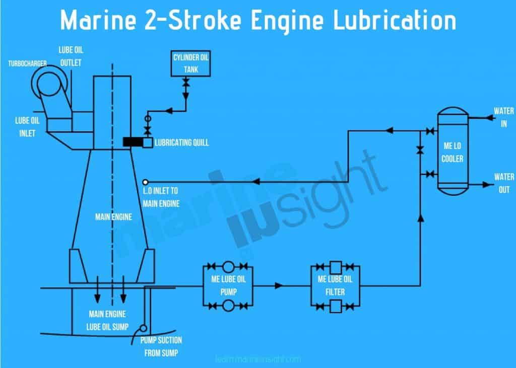
Ship's Main Engine Lubrication System Explained
Warning: Oil filters have an internal one-way check valve. If oil lines are hooked up backward, oil flow to the engine is stopped. Engine failure will result. M-6880-M50 Oil Line Adapter Top hole is oil from the remote mount oil filter adapter INTO the engine. (Oil port A, IN) Bottom hole is oil coming OUT of the engine going into the oil filter.

which way does oil flow? - 987-1 Series (Boxster, Boxster S ...
Engine Oil Flow. Blog. Jan. 8, 2022. Big Ideas in sales: A look at what's next for better sales kickoffs and presentations

Cummins- Oil flow diagram in engine. - YouTube
12.12.2013 · Oil pressed at this temperature below 49°C (120°F) is known as "cold-pressed" oil and is desired for alleged increased nutritional properties. Cold-pressed oil is also important if the oil is to be used directly as engine fuel because an oil pressed at a lower temperature carries lower levels of phosphorous. High levels of phosphorous in the ...

Vw Full Flow Oil System Diagram - Wiring Site Resource
Diesel Engine Fundamentals DOE-HDBK-1018/1-93 REFERENCES REFERENCES Benson & Whitehouse, Internal Combustion Engines, Pergamon. Cheremisinoff, N. P., Fluid Flow, Pumps, Pipes and Channels, Ann Arbor Science. Scheel, Gas and Air Compression Machinery, McGraw/Hill. Skrotzki and Vopat, Steam and Gas Turbines, McGraw/Hill.

CAT Engine Course (Part 5) Lubrication System
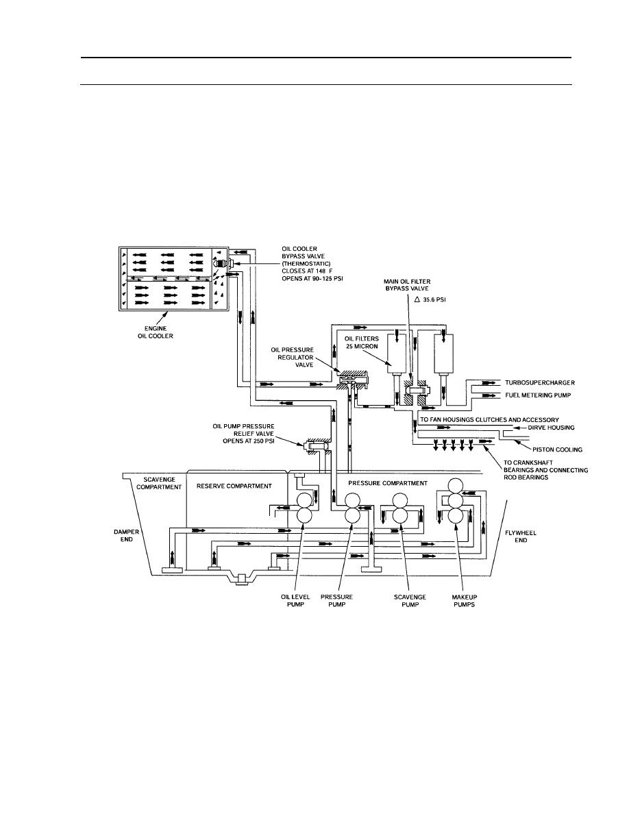
Flow Diagram 1. Lubricating oil flow from oil pump 2. Thermostat 3. Flow through oil cooler 4. Lubricating oil cooler flow return to filter head 5. Filter bypass valve 6. Oil filter 7. Flow to turbocharger 8. Flow to main oil rifle 9. Oil drain from turbocharger 10. Thermostat open - oil flows through oil cooler 11. Thermostat closed - oil ...
NEED HELP! Oil system diagram with oil flow direction ...
Upper engine oil returns via holes in the valley that drain oil back into the sump. This system works fine for street applications, but at high speeds, power is lost when oil draining back contacts the spinning crankshaft. The small-block is often modified to redirect return oil to the front or rear of the block, where large drain-back passages ...

Wolflubes - The Vital Lubricant - Blog - The basics of ...
As the oil travels through the element plates, it is cooled by engine coolant traveling past the outside of the plates. It is then routed to the oil filter head and through a full flow oil filter. If a plugged filter is encountered, the filter by-pass valve opens, allowing unfiltered oil to lubricate the engine.

Fuel Oil System Diagram on Ship with Diagram Marine Diesel Engine
12-08-2011, 06:06 AM. I think I have seen an oil flow diagram in the TIS. If you are curious as to how the oil cooler works, I can tell you that. Oil from the pump comes up to the oil filter adapter. Depending on engine temperature oil then goes through the filter and on to the engine or through the cooler then through the filter and on to the ...

Engine - Oil System | Alfaholics
21.07.2020 · To avoid this problem, changing engine oil and filter is very necessary within some period of time. Oil filter: The oil filter helps to keep small particles, separating them from the oil so that clean oil can flow to the engine parts. The oil pump allows the oil flow through the oil filter to the galleries before reaching the engine parts.
Vehicle Fluids
Oil flows from the camshaft into the valve inlet #3 through the internal check ball and filter. Oil exits the valve #2 and travels within the internal passages of the camshaft into the entry ports #7 of the actuator. The center oil groove of the actuator is pressurized and oil reenters the valve #1.

Oil System Differences: Wet vs. Dry Sump - Know Your Parts
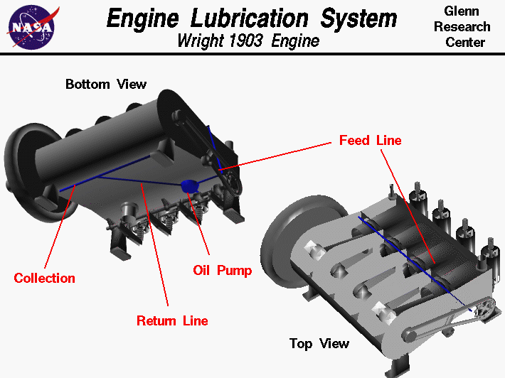
The flow of oil through a Lycoming reciprocating aircraft engine is known to be a necessary function during the operation of the engine. Pilots are often not at all concerned about how this function occurs, as long as the oil pressure and oil temperature indicators show a proper reading. A&P mechanics, on the other hand, often need to know how the system works and what parts

Engine Oils and Their Filters | Purdue Pesticide Programs
Process Flow Diagram Symbols Chemical and Process Engineering solution contains variety predesigned process flow diagram elements relating to instrumentation, containers, piping and distribution necessary for chemical engineering, and can be used to map out chemical processes or easy creating various Chemical and Process Flow Diagrams in ConceptDraw DIAGRAM.
Oil flow Route | Lancer Register Forum
Need an oil schematic for my '13 Silverado. ASAP. Ideas on where to find it? Thanks! Edited add - REASON is I need to understand the oil flow to the pressure sending unit and the little screen there, and the relationship to the rest of the oil system. Also, is this a full-flow filter system, or is there a bypass, or what?
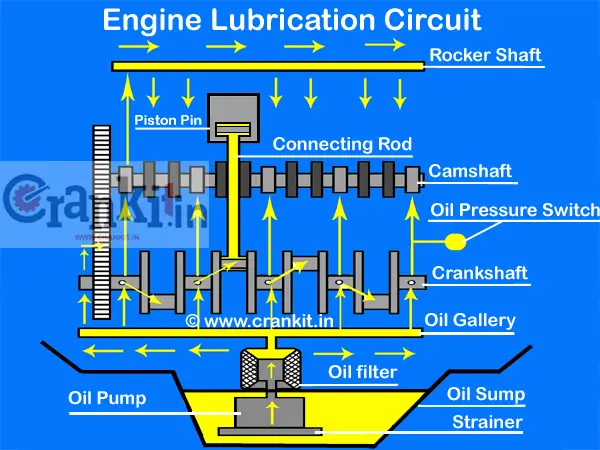
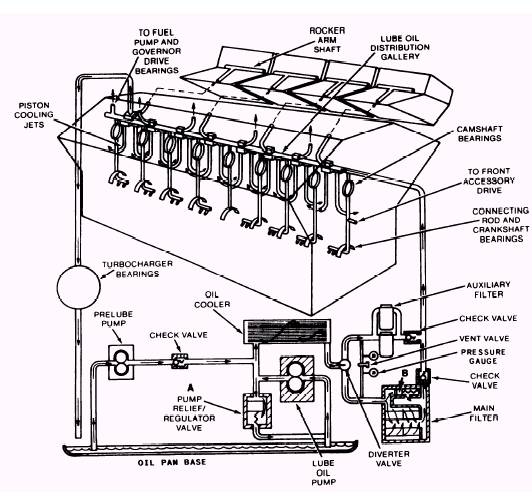
Engine Lubrication System
One key point in the oil flow path is at the right rear corner of the engine block. Here there is a special fitting where the external oil line connects. The longitudinal oil gallery passes through the cross drilling at the back of the block where this fitting connects.

Atv Line Art Engine Oil Diagram Stock Photo - Download Image ...
05.04.2000 · This diagram shows details of how a cooling system and the plumbing is connected. HowStuffWorks The cooling system in most cars consists of the radiator and water pump. Water circulates through passages around the cylinders and then travels through the radiator to cool it off. In a few cars (most notably pre-1999 Volkswagen Beetles), as well as most motorcycles …
Engine Oil Flow
There are several factors which contribute to the lower efficiency of the IDI engine (Monaghan, 1982): (i) combustion tends to continue until later in the expansion stroke: this is partly because injection usually starts later and partly because combustion takes longer in a pre-chamber engine; (ii) pumping losses are greater on account of the flow through the throat; (iii) heat …
How Does The Engine Lubrication System Work? Know Here ...
In this short animation I briefly explain how the oil flows through an engine when its started after an oil change.#oil#engine#howitworks#GarageTech#circulat...

Gas Turbine Engine Oil System Overview
6.0 Powerstroke Oil System Diagram. 1 on page 38 shows a simple oil flow schematic for the L diesel engine. In order for the fuel injectors to operate, a minimum of psi oil pressure is required. The oil is the life blood of the L diesel as the injectors are The oil is run through a low pressure oil pump which pushes oil to the oil filter at.

Vehicle Lubrication System infographic diagram showing cross ...
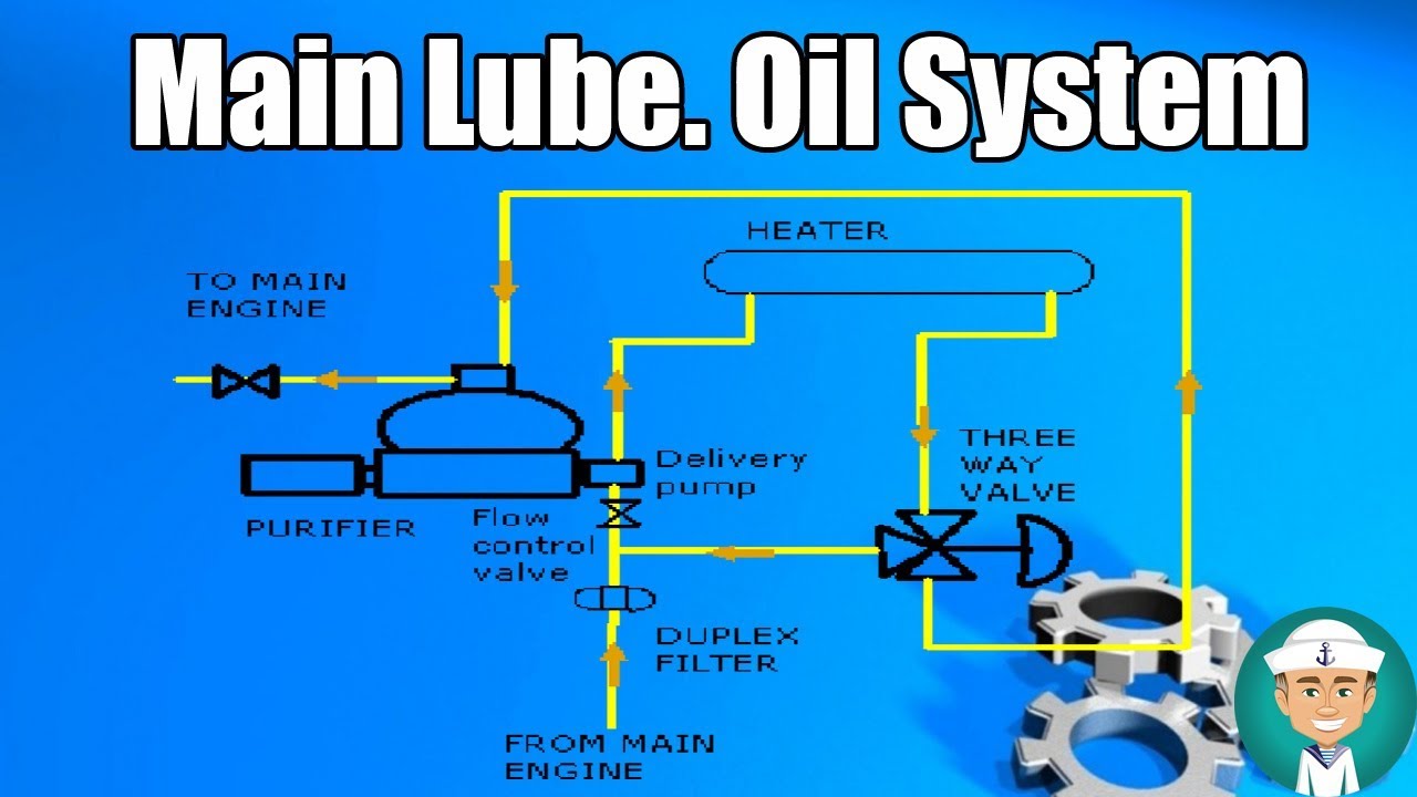
Main Lubricating Oil System

B737Theory - CFM 56-7b oil. The engine oil system... | Facebook
Kawasaki Ninja Service Manual: Engine Oil Flow Chart - Engine ...
Kia Picanto - Engine Oil - Lubrication System

Engine Lubrication Basics – Auto Repair Help

3L engine oil flow and coolant flow chart MB – Brooklyn ...
Lubrication System
Hyundai Azera: Engine Oil Flow Diagram - Lubrication System ...
Kia Carens - Flow diagram - Lubrication System

Engine Lubrication System | Turbomachinery blog

DG & ME FUEL OIL SYSTEM DIAGRAM
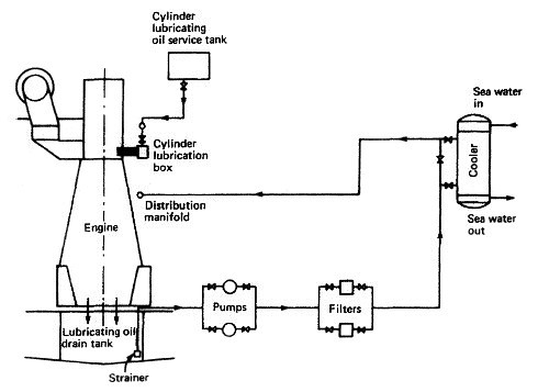
Lubricating Oil System for Marine Diesel Engine
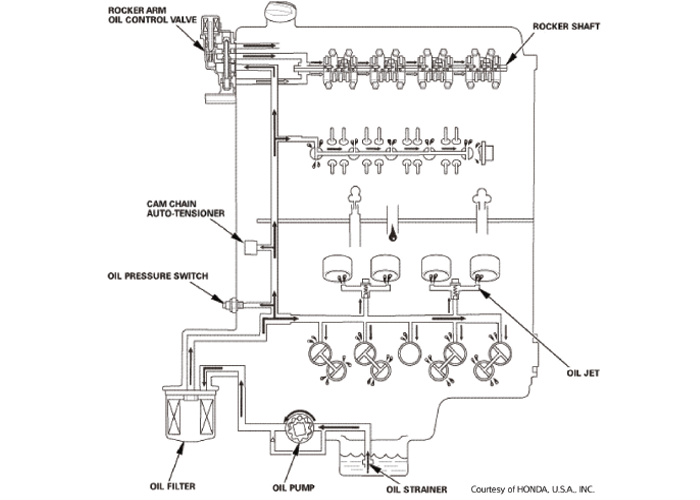
Honda Oil System Inspection Procedures
Full-flow lubricating oil system
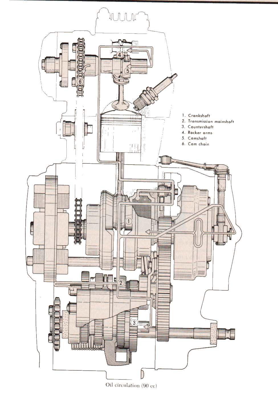
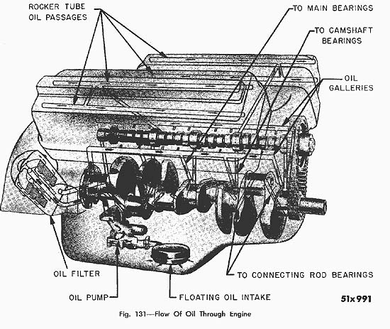
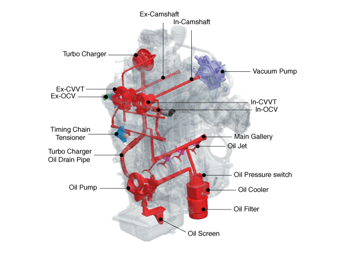
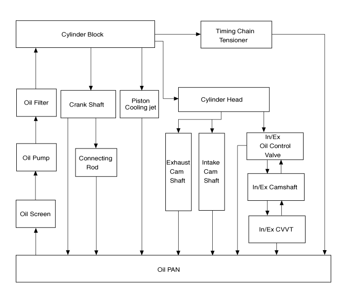
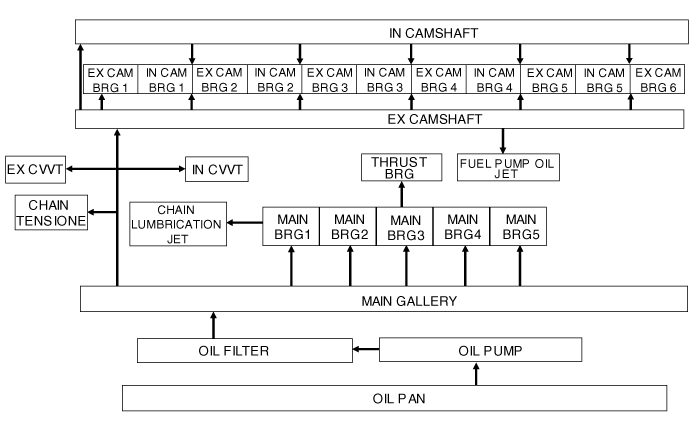
ENGINE OIL FLOW DIAGRAM

Basic Engine Oil Knowledge | ENEOS Global | ENEOS Corporation


Comments
Post a Comment