39 wireless charger circuit diagram pdf
Wireless charging uses electromagnetic fields to transfer power from a transmitter to a receiver application to charge the battery. This erases the need for ... wireless charging is popular, and widely used in ... Figure 8 shows the schematic of a full-bridge inverter used by the wireless charger transmitter. The.
Band of blockers,rooftop jamming equipment wholesale,News courtesy of CANSPACE Listserv. Starting December 31, 2014, the Air Force 2nd Space Operations Squadron began transmitting daily CNAV uploads. The CNAV signals should continue to be...
Wireless charger circuit diagram pdf
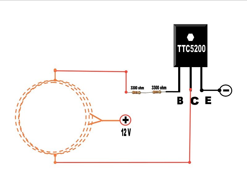
Thus two conductors are said to be inductively coupled. Wireless Power Transfer Circuit Diagram: Wireless Mobile Charger Circuit Diagram Wireless Mobile Charger ... Cell phone emf blocker,blocked cell phone numbers,In November, December, and January, a regulatory drama with high potential impact on the GPS signal and domestic U.S. GPS users began unfolding before the Federal Communications Commission (FCC). As... Blocking gps signal,uber fake gps 2018,Spirent Communications plc, a manufacturer of test equipment and services for improving positioning, navigation and timing (PNT) system performance, today announced the new Spirent GSS6450 RF record...
Wireless charger circuit diagram pdf. Hello, I’m very new to circuit design and I’m trying to copy a circuit on a pcb that I have into a circuit diagram so I can better understand it. Doing this has been extremely hard. I’ve just been trying to copy over the exact trace layout onto a piece of paper but i’m unable to mark the components and it’s extremely messy. Should I suck it up and just try harder or is there an easier way to do this? Thanks I have a lab report where I want to investigate how the length of copper wire affects the charging rate of an iPhone, so I'd like to buy a [Qi Wireless Charger Circuit](https://www.amazon.com/Gikfun-Wireless-Charger-Circuit-Charging/dp/B073W7P5T8) and then cut off the coil that's pre-installed, and connect my own copper coil. Would this be feasible? I have 200W-15V solar panel. I want to charge 90A - 12V battery from it. Can i get a circuit diagram for that. Jul 3, 2019 - The project Wireless Mobile Charger Circuit Diagram posted here can deliver 271mA at 5.2V so you charge mobile phone and also can be used to ...
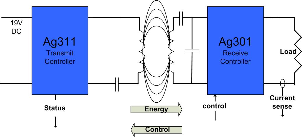
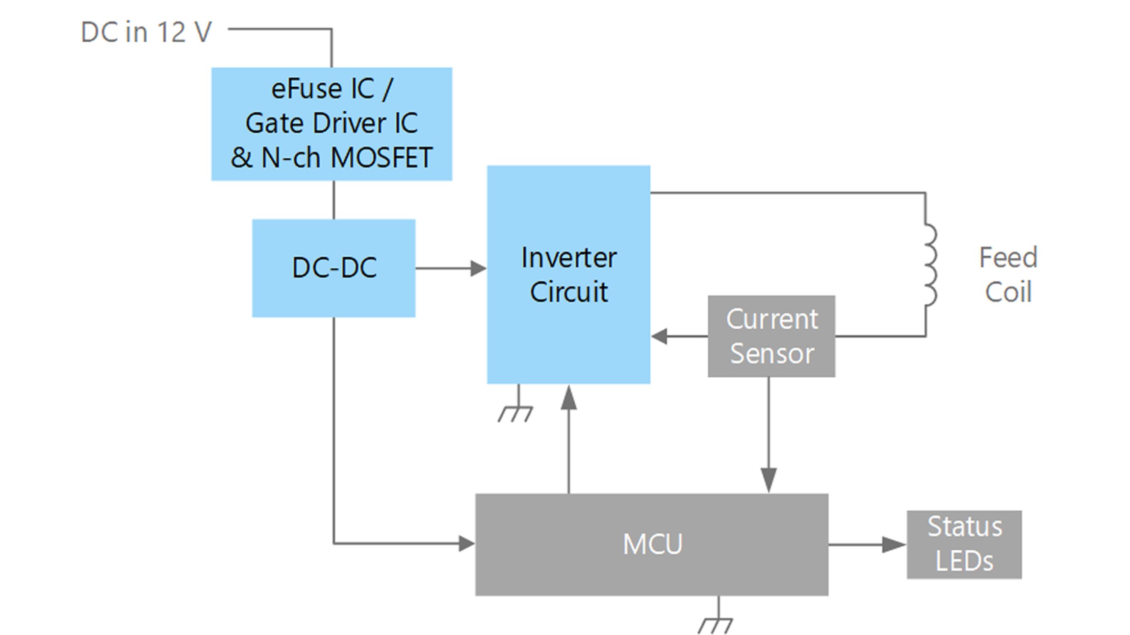
the transmitter circuit is AC to the DC correction circuit and then it is controlled by ... Figure 1.3: Block diagram of wireless power transfer system. 17.10.2017 ... need to place their adapter circuit to charge the mobile phone. ... The block diagram of wireless mobile charger consist of. I have experience of building DC adapters before, and I have some idea on how to build this 7s Li-ion charger, but it's not as good as commercial ones, but they are expensive. So. I am trying to make a magic system which relies on magic circles, magic language, grimoires, geometry, etc... for a game. So I want to be a bit puzzle-like, easily understandable yet quite versatile. My idea was to make them like Electronic Circuits, with a magic source representing a battery or an AC source, some parafernalia in the middle that transforms magic energy into other types of energy(maybe elemental magics since I want my system to be elemental) then ground it. Since Electron...
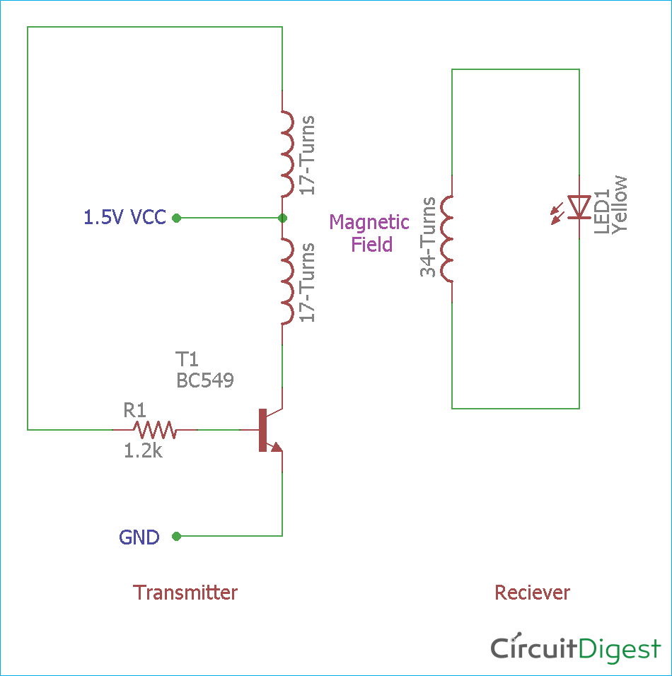
15 Apr 2017 — Wireless Mobile Charger uses the inductive coupling principle. In this principle, two LC tuned circuits communicate at the same tuned frequency ... 01.04.2021 ... Also, in our previous post we comprehensively learned the basics of wireless charging, we'll take the help of the instructions presented there ... I'm looking at "[https://www.allaboutcircuits.com/technical-articles/implementing-multiplexers-with-pass-transistor-logic](https://www.allaboutcircuits.com/technical-articles/implementing-multiplexers-with-pass-transistor-logic)" with title "Implementing Multiplexers with Pass-Transistor Logic" by Robert Keim. Under label "The Transmission Gate Multiplexer" I see the circuit diagram I'm adding in the comments. Is it unreasonable to assume a five volt value for logic one and a zero volt value for... Jul 3, 2019 - The project Wireless Mobile Charger Circuit Diagram posted here can deliver 271mA at 5.2V so you charge mobile phone and also can be used to ...
6 Useful Dc Cell Phone Charger Circuits Explained Homemade
Car key signal blocker,signal blocker kaufen sie,Steve Malkos, Android Context Group, Google We've come a long way since the inception of GPS. Today, location often is taken for granted, but that's true of every mainstream technology. It's...

woman in black and white stripe shirt walking on dirt road between green plants during daytime
by R Jin · 2014 · Cited by 2 — Table 3.1 summarizes the design objectives for this work. 3.1.3 Design Overview. Figure 3.1: Adaptive wireless charging system general diagram. To address the ...

LTC4120 Wireless Power Receiver and 400mA Buck Battery ...
22.12.2019 ... PDF | This system demonstrates the concept of wireless mobile charging system using ... Block diagram of wireless mobile phone charger [17].

Wireless Charger Diagram - Wireless Charging Paused S10
Car anti-tracker gps signal blocker,gps blocker Bois-des-Filion,Some ups and downs for unmanned aircraft this month — good news that there is further progress on the pseudo-satellite front, but we also have MIL-SPEC drones lost to shoot-downs and recent crash...

blue bmw m 3 coupe on gray asphalt road during daytime
Tightly coupled wireless charging technology uses magnetic induction to transfer power ... The field works through air, no magnetic circuit links the coils.37 pages
Wireless Charger Diagram - Wireless Charging Paused S10
Blocking gps signal,uber fake gps 2018,Spirent Communications plc, a manufacturer of test equipment and services for improving positioning, navigation and timing (PNT) system performance, today announced the new Spirent GSS6450 RF record...

Wireless Charger Circuit - Circuit Diagram Images in 2020 ...
Cell phone emf blocker,blocked cell phone numbers,In November, December, and January, a regulatory drama with high potential impact on the GPS signal and domestic U.S. GPS users began unfolding before the Federal Communications Commission (FCC). As...

flock of birds flying under white clouds during daytime
Thus two conductors are said to be inductively coupled. Wireless Power Transfer Circuit Diagram: Wireless Mobile Charger Circuit Diagram Wireless Mobile Charger ...

High Current Wireless Battery Charger Circuit

make yourself a d c mobile charger - Gallery Of Electronic ...

Mobile Charger Pcb Diagram / Inverter Protection Circuit ...
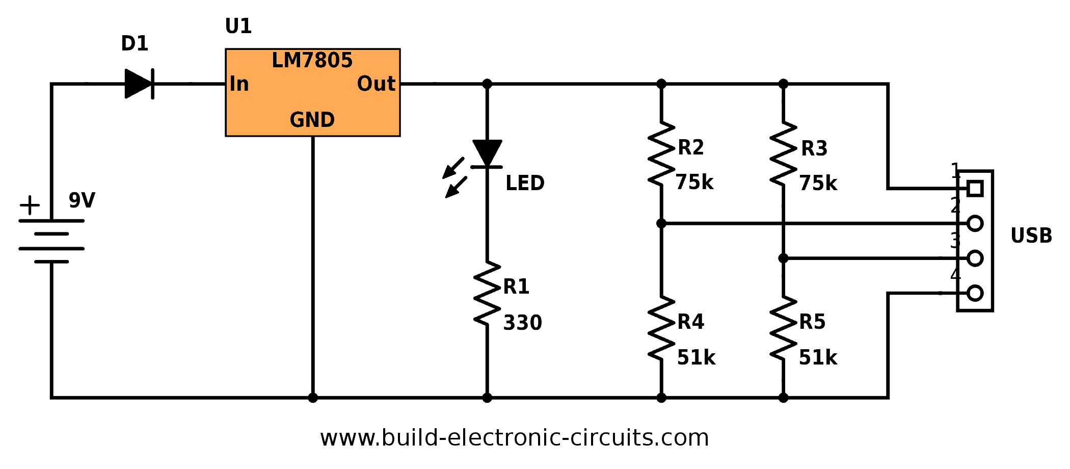
Portable USB Charger Circuit - Build Electronic Circuits

Wireless Charger Diagram - Wireless Charging Paused S10

All Mobile Phones Schematic Diagram Pdf - Circuit Diagram ...

Wireless Charger Circuit - Circuit Diagram Images ...

Mobile Phone Charger Circuit Diagram Pdf 2020 | Indolink.Me

gray and red car on roadway during day time

Car Mobile Phone Charger Circuit

Wireless Cellphone Charger Circuit

12V Battery Charger | Battery charger circuit, Battery ...
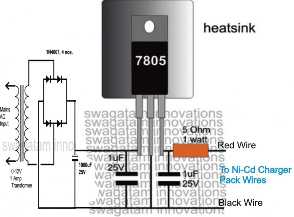
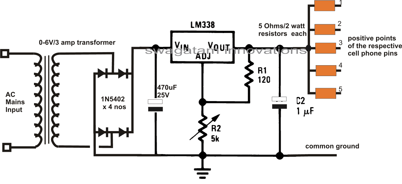
Cell Phone Emergency Charger Pack using Ni-Cd Batteries ...

Pin on Electronics

(PDF) Software-Based Wireless Power Transfer Platform for ...

yellow porsche 911 on road
Wireless Electricity Transfer Project - Step by Step ...
Wireless Power Transmission Circuit Diagram Project Pdf ...

Wireless Charger Diagram - Wireless Charging Paused S10

Generic block diagram of a wireless power system | Circuit ...

Wireless Charger Circuit - Circuit Diagram Images ...

Verizon Refurbished Phones Near Me: Circuit Diagram Of A ...

Chip de carga inalambrica - Ciencia y Educación - Taringa!

(PDF) A development of electrical vehicle charging system ...

Wireless Cellphone Charger Circuit

white and black car on road

Usb Wiring Diagram 12V : 12v Usb Wiring Diagram Speaker ...

Wiring Diagram | Wireless Inductive Power Night Light ...

Introduction to Wireless Battery Charging | IDT
USB Mobile Charger Circuit Diagram
Wireless Charger Diagram - Wireless Charging Paused S10


Comments
Post a Comment