39 universal joint diagram
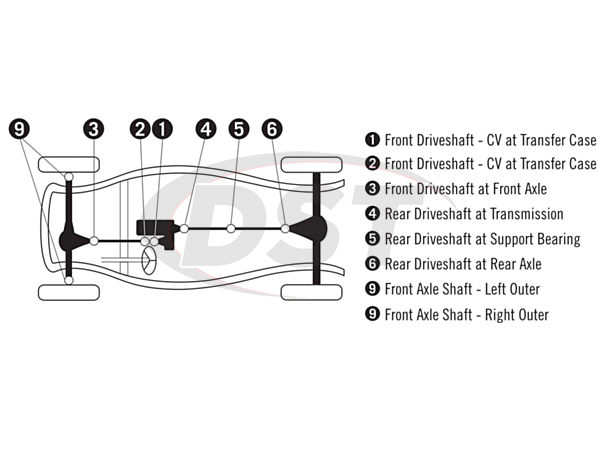
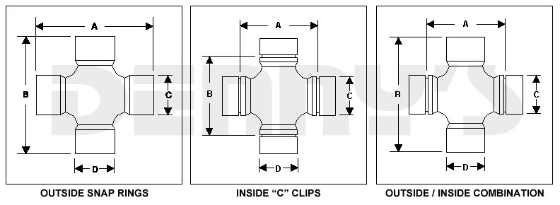
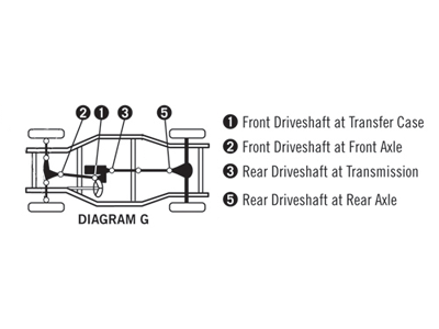
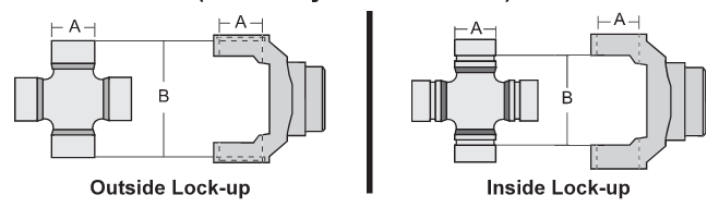
U-joints can be located along driveshafts, 4WD transfer case shafts, and even axle shafts. U-joints are different in design from constant velocity joints. Also described as Cardan joints or Spicer Joints. U-Joint Strap. U-joint straps are a style of bracket used to secure a cross piece to a driveshaft yoke. Click Diagram. Basic U-Joint Series Identification made easy. Important notes on Inside lock up U-Joints. Pinion Yokes With Tabs. Click on the diagram to see pinion yoke with tabs. If you are needing a new pinion yoke, this will show what information we need to check. << View Images or click here to save/send>>Pinion Yoke w-Tabs 2011.pdf
May 14, 2019 · Universal. A universal joint is shown in figure 7. Figure 7: A universal joint. A universal joint is like a ball and socket joint that constrains an extra degree of rotational freedom. Given axis 1 on body 1, and axis 2 on body 2 that is perpendicular to axis 1, it keeps them perpendicular.
Universal joint diagram
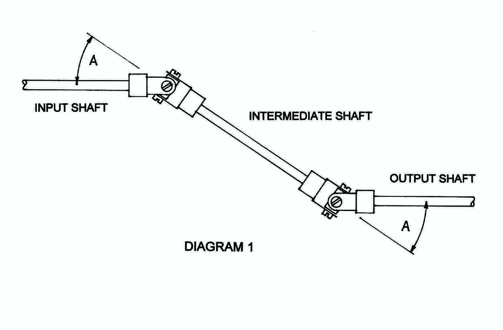
UNIVERSAL JOINTS 1.0 GENERAL A universal joint is a positive, mechanical connection between rotating shafts, which are usually not parallel, but intersecting. They are used to transmIt motion, power, or both. The simplest and most common type is called the Cardan joint or Hooke joint. It is shown in Figure 1. It consists of two yokes, one on ... Step 2: Measure Bearing Caps. Tip: Measure two adjacent caps even if they’re the same style in case they are different sizes. Step 3: Measure U-joint assembly. Refer to chart in Step 1 for correct style. Plain round bearings, knurled round bearings and slotted round bearings: Remove grease boots, ensure caps are fully seated by applying light ... Feb 12, 2016 · Fig. shows, the Fe-C equilibrium diagram in which various structure (obtained during heating and cooling), phases and microscopic constituents of various kinds of steel and cast iron are depicted. The main structures, significance of various lines and critical points are discussed as under. 1. Structures in Fe-C-diagram
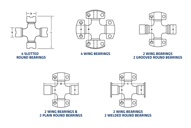
Universal joint diagram. PART DESIGN & ASSEMBLY (UNIVERSAL JOINT) From this diagram we have to know, Selection of plane Sketching the line and circle Constrain the dimension Symmetricity Mirror line object Trim the profile Exit work bench Pad the profile Pocket Project element Edge fillet Views Pan Zoom fit Using a pain diagram to map out the location of the pain is often very helpful in diagnosis. SI joint pain is commonly found 10 cm caudally and 3 cm laterally from the patient's posterior superior iliac spine. SI joint pain is commonly referred to the … This universal joint design uses a block- or wing-style bearing cup that locates in a flat flange-type yoke with a tongue and groove arrangement. Identify the bearing shape on the previous diagram. Some applications use two different bearing types. 1. Assemble bearing cups onto cross. 2. Clamp the bearings with C-clamp or vise. The Concept and Importance of Universal Joint Phasing and Drive Shaft Alignment. Phasing is the process of aligning the universal joint yokes on both ends of the drive shaft (or double u-joint)in a parallel fashion. If the joints are not properly phased, they will operate at varying speeds throughout each revolution which can cause second-order ...
Machine Service, Inc. 1000 Ashwaubenon Street Green Bay, WI 54304 Toll Free: 800-677-8711 Phone: 920-339-3000 Fax: 920-339-3001 slide the u-joint over shaft until it is fully engaged in the joint (Borgeson Universal recommends 7/8”–1” engagement). Use a marker to make a mark through each hole in the joint. Remove the joint. Using a quarter inch drill bit, spot the shaft where the setscrews will seat. Re-install the joint and install setscrews and jam nuts. Knuckle Joint - Parts, Diagram, Design Calcuation, Applications Knuckle Joint A knuckle joint is used to connect two rods which are under the action of tensile loads. However, if the joint is guided, the rods may support a compressive load. Sep 06, 2021 · A universal joint is considered the oldest of all flexible couplings.It is commonly known for its application in automobiles and trucks. It is located where two shafts are to be joined at an angle to transmit torque.
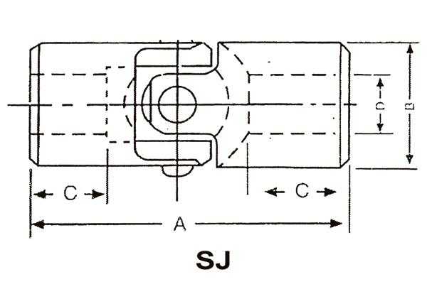
U-Joint Identifier: Use this simple form to find your U-Joint series from your U-Joint dimensions. You will need to know your cap diameter and u-joint width. OR you can find your u-joint dimension if you know your series. Free ground shipping on all driveshafts and orders over $100 within the continental USA! The Q-value in Figure 1 is related to the total amount of support (temporary and permanent) in the roof. The diagram is based on numerous tunnel support cases. Wall support can also be found using the same figure by applying the wall height and the following adjustments to Q: For Q > 10 use Q. wall = 5Q . For 0.1 < Q < 10 use Q. wall = 2.5Q The universal joint, one of the earliest means of transmitting power between two angled shafts, was invented by Gerolamo Cardano in the 16th century. The fact that it failed to maintain constant velocity during rotation was recognized by Robert Hooke in the 17th century, who proposed the first constant velocity joint, consisting of two Cardan joints offset by 90 … Sep 06, 2021 · 1. U-joint. A universal joint (U-joint) is a mechanical joint used to connect rotating shafts. Nowadays, the driveshaft and universal joints are mostly seen on rear-wheel drive and four-wheel drive vehicles. 2. Tube. A tube is a part of a drive shaft, It is often used in front engine and rear drive automobiles.
U Joint Package - Dodge Ram 1500 4WD 06-08 (Mega Cab Only)
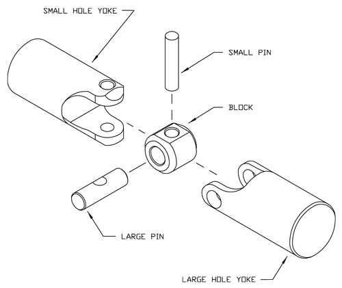
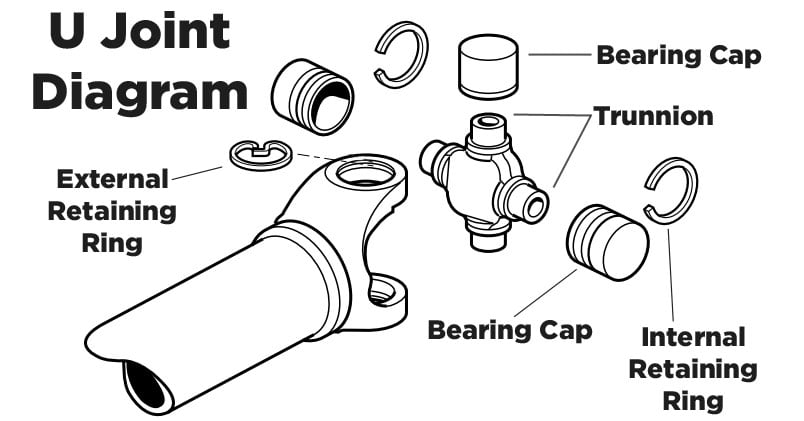
A universal joint in its simplest form consists of two shaft yokes at right angles to each other and a four point cross which connects the yokes. The cross rides inside the bearing cap assemblies, which are pressed into the yoke eyes.

Assembly Universal Joints and Drive Shafts | JW Winco ...
A universal joint (universal coupling, U-joint, Cardan joint, Spicer or Hardy Spicer joint, or Hooke's joint) is a joint or coupling connecting rigid rods whose axes are inclined to each other, and is commonly used in shafts that transmit rotary motion.It consists of a pair of hinges located close together, oriented at 90° to each other, connected by a cross shaft.

SPL - 5-1310-1X - Universal Joint
Feb 12, 2016 · Fig. shows, the Fe-C equilibrium diagram in which various structure (obtained during heating and cooling), phases and microscopic constituents of various kinds of steel and cast iron are depicted. The main structures, significance of various lines and critical points are discussed as under. 1. Structures in Fe-C-diagram
Assembly Instructions For Universal Joints | Belden Universal
Step 2: Measure Bearing Caps. Tip: Measure two adjacent caps even if they’re the same style in case they are different sizes. Step 3: Measure U-joint assembly. Refer to chart in Step 1 for correct style. Plain round bearings, knurled round bearings and slotted round bearings: Remove grease boots, ensure caps are fully seated by applying light ...
Universal Joints Explained by Peter Stuart | Meccano ...
UNIVERSAL JOINTS 1.0 GENERAL A universal joint is a positive, mechanical connection between rotating shafts, which are usually not parallel, but intersecting. They are used to transmIt motion, power, or both. The simplest and most common type is called the Cardan joint or Hooke joint. It is shown in Figure 1. It consists of two yokes, one on ...

Universal joint - Wikipedia
Universal Joint Couplings,Universal Coupling Manufacturer
Universal Joint
Driveline Master Catalog

Universal Joint - Types, Working, Application & Diagram
Universal Joints for cars, light, medium and heavy duty ...

General Universal Joint Characteristics and Applications from ...

U-Joint (3/4"-20 spline x 3/4"-20 spline) – Kaz Tech FSAE
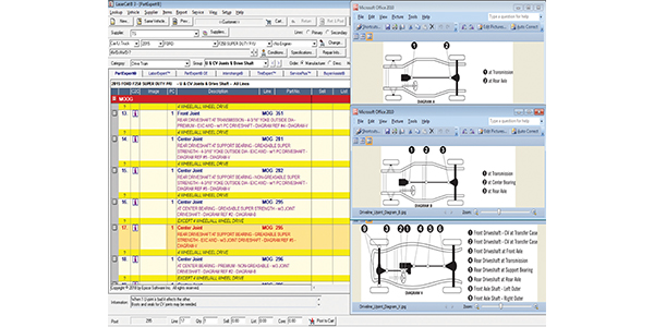
Detailed MOOG U-Joint Diagrams Latest User-Friendly Research ...
![What is a Universal Joint? Parts, Types, Working & Uses [PDF]](https://www.theengineerspost.com/wp-content/uploads/2021/08/universal-joint-min.jpg?ezimgfmt=rs:352x191/rscb19/ng:webp/ngcb19)
What is a Universal Joint? Parts, Types, Working & Uses [PDF]
Finding the Right Replacement U-Joint | MOOG Parts
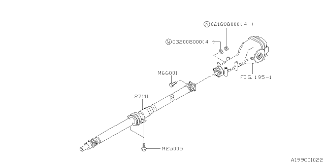
27031FC030 Genuine Subaru Universal Joint / U-Joint

Universal joint - Wikipedia

Universal Joint Maximum Minimum Speed | Engineering Reference ...
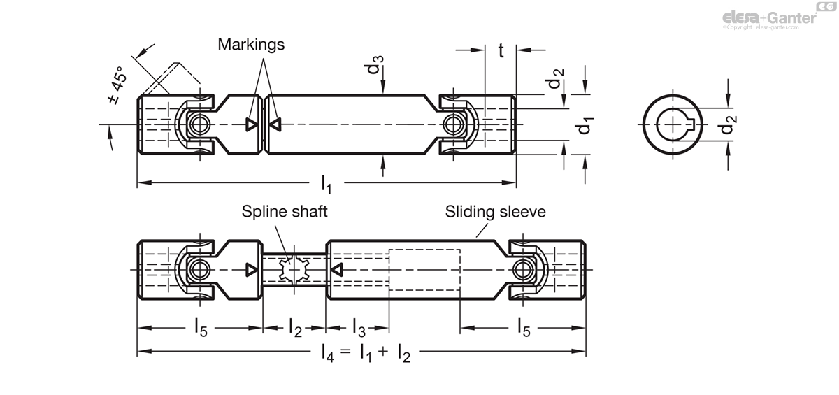
GN 808.3 Universal joint shafts with needle bearing | Elesa+ ...

U-Joint Sizes and Strength Comparison | Universal Joints

Universal Joint - Types, Working, Application & Diagram
Symptoms of Bad U Joints | Suspension.com

Drafting of Universal Joint Parts – Machine CADD

Snapper 7080499 - 54" Mower Attachment (MF) Parts Diagram for ...
U Joint Package - Toyota Tacoma 95-04 4WD

Quick Release Universal Joints| Springfix Linkages.

Universal Joints - an overview | ScienceDirect Topics
Universal Joint Table

Servis Rhino V152 MOWER V152 SNCS0100259406 -CURRENT CENTER ...
![What is a Universal Joint? Parts, Types, Working & Uses [PDF]](https://www.theengineerspost.com/wp-content/uploads/2021/08/Universal-Joint-min-1.jpg)
What is a Universal Joint? Parts, Types, Working & Uses [PDF]
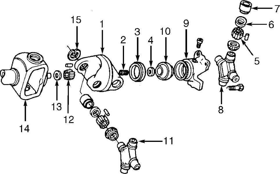
DRIVE SHAFT & UNIVERSAL JOINTS :: 1993 :: Jeep Cherokee (XJ ...

Virtual Labs

Universal Joints (Automobile)

Steering Shaft and U-Joint Selection Guide
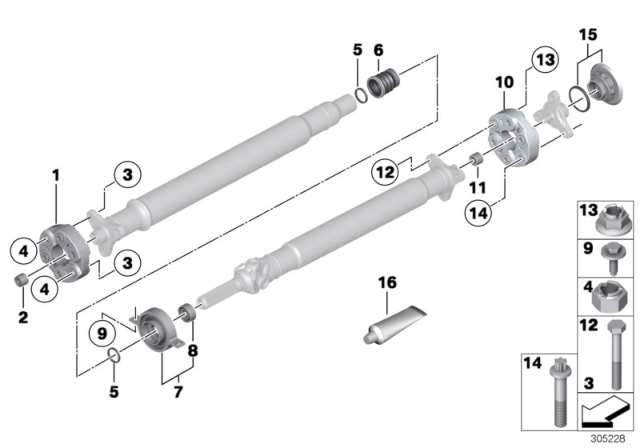
26118681477 Genuine BMW Universal Joint

G&G Manufacturing Company - Complete U-Joints

65160.W0016 - Double Universal Joint | Wixroyd

Details about FORD OEM 93-97 Ranger Carrier Front Axles-U-joint Seal Left E4TZ3254B


Comments
Post a Comment