39 century ac motor wiring diagram 115 volts
Does anybody know which wires correlate to which features on the bafang hub motors? Doing some surgery here and I’m just trying to pinpoint which wires are responsible for the direction of the motor rotation. Also how to reverse the rotation if needed Thanks! Wondering if someone could post a wiring diagram for the Mantis 10 Elite as I finished replacing a damage disc brake rotor and ive wired the front wheel wrong and now it spins backwards 😂 Since I’d rather not just unplugged it and try something different I’d prefer to look at the diagram and fix it correctly Thanks
Hello. Anybody here who knows or has a wiring diagram for a Coswheel FTN T20 ebike? I need help on how to rewire and add turn signal lights on the front and back. It has already the turn switch on the handle bar. Just need to know where the wires to connected or it's a plug and play. The bike has a 500 watts rear hub motor and a 48 volts 15 ah battery. Any help is much appreciated. Thanks all.

Century ac motor wiring diagram 115 volts
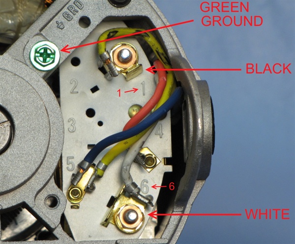
I have a three prong cable that I'm trying to wire to a motor http://imgur.com/a/zyLgw The diagram and everything is in that link. The power will come from an industrial programmable controller (Chrontrol). Do I just wire black/white to L1 L2 and ground to the green nut seen in the picture? http://imgur.com/a/RHFodBY I have a three prong cable that I'm trying to wire to a motor http://imgur.com/a/zyLgw The diagram and everything is in that link. The power will come from an industrial programmable controller (Chrontrol). Do I just wire black/white to L1 L2 and ground to the green nut seen in the picture?
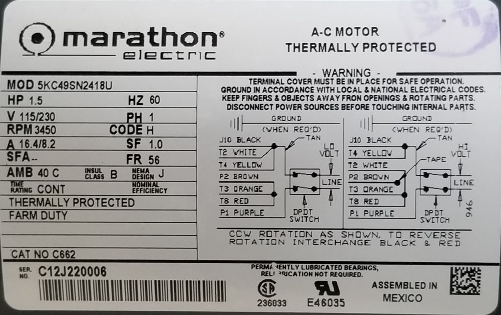
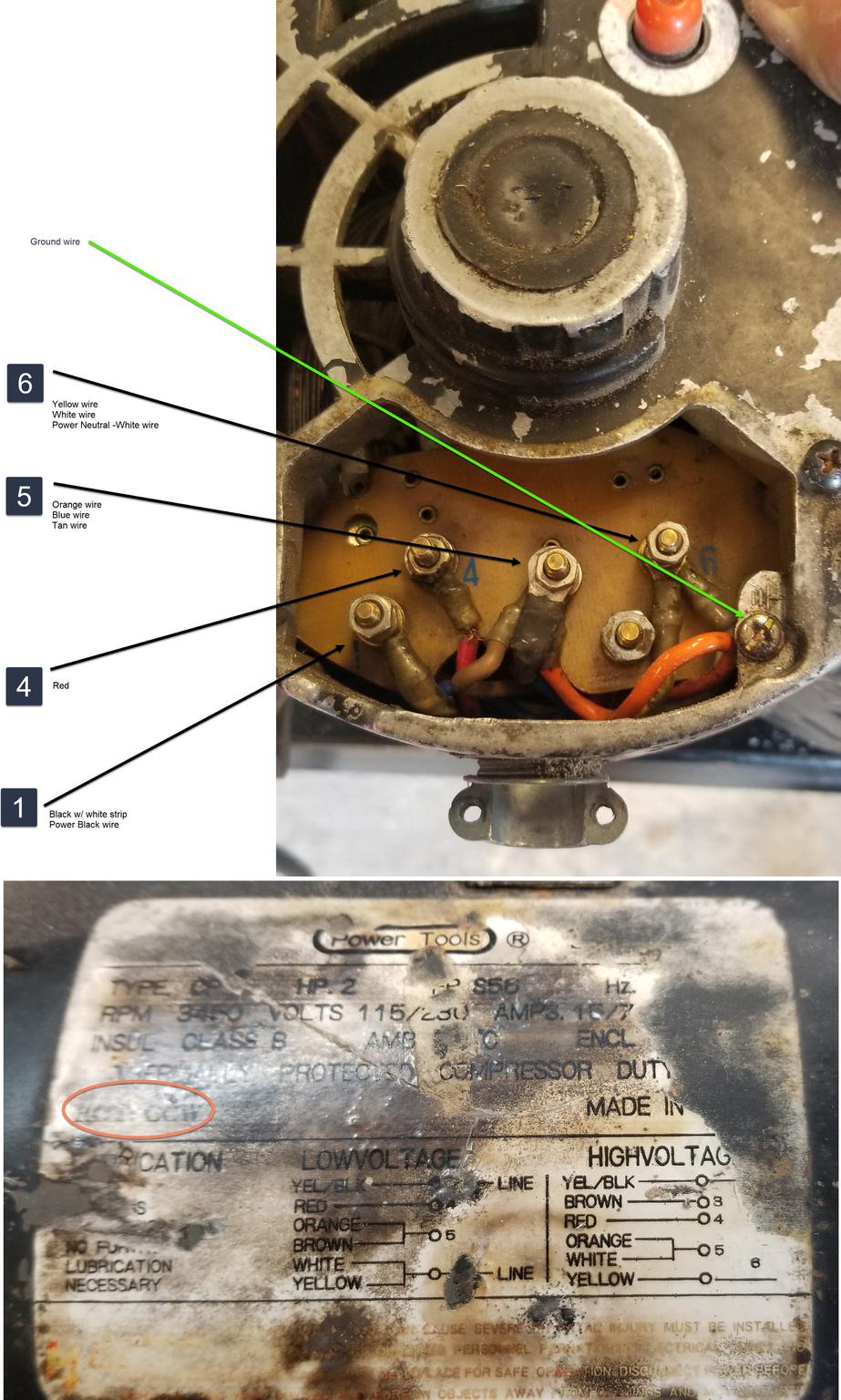
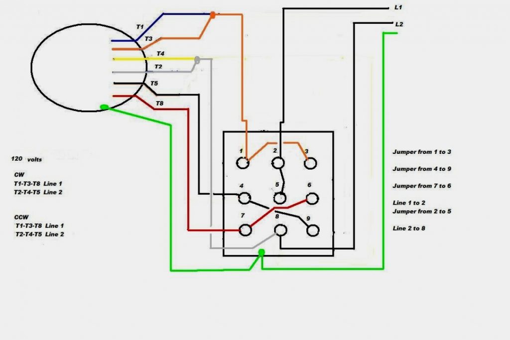
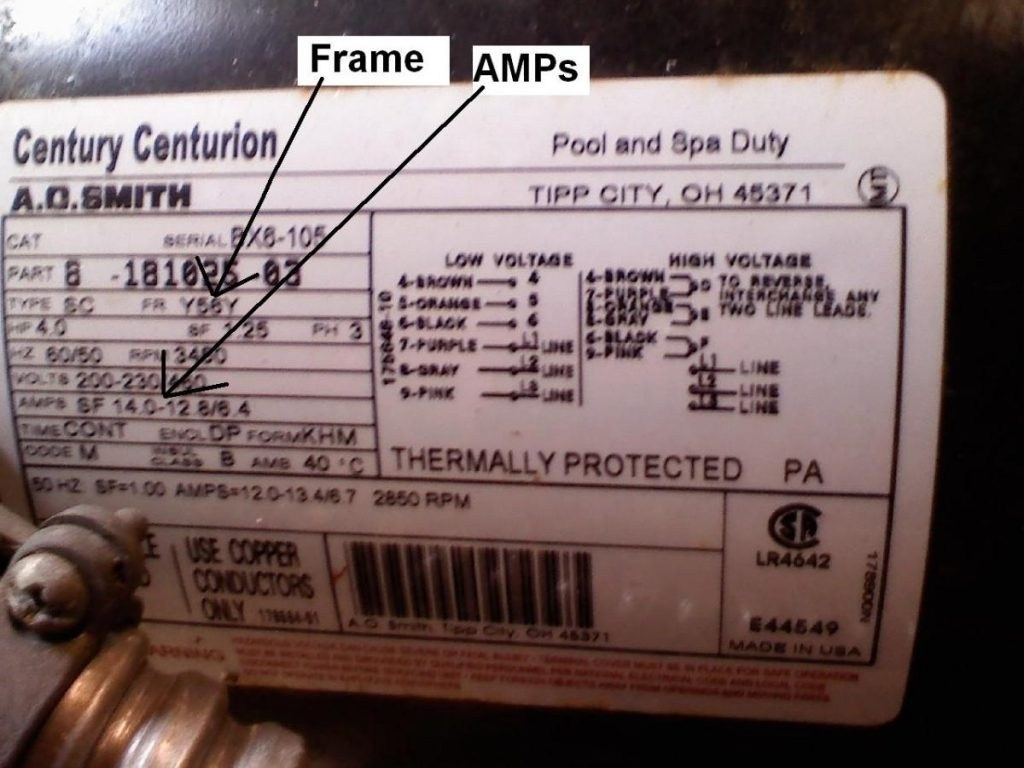
Century ac motor wiring diagram 115 volts. ​ [T9 connects from SINPAC switch to ?](https://preview.redd.it/ftdgzxh6b4c81.jpg?width=1057&format=pjpg&auto=webp&s=5c10b64d8c1a0cab95ecdeb687d971c9cea07578) Does anyone know of a wiring diagram of the stock Rhino Fire harness? I'm curious what some of these small boards and the switch behind the left side Scotch yoke are used to control/sense. I'd also like to replace the flywheel motors, but it seems none of the dual-shaft motors I found have long enough output shafts to make it work. I noticed that a few people have made conversions to 4-motor 2-cage setups, but I'm trying to do this relatively simply since it's going to be stock performance, I ... I bought a 1970s era Delta jointer. Ran great on 230. Rewired it to 115 per the wiring diagram. Now the motor spins backwards. Any ideas? Thanks! Hi - I have a older GE motor #5KC49BB514EX. I'm trying to find out the year it was made and also a wiring diagram. The second picture shows the wiring box - if that's what you call it. On the top right, there is a red (bare) wire coming out of the motor housing. On the bottom left there is a black wire with tape coming out of the housing. There are 4 terminals from the top 1 through 4. Any help would be great. Thanks
I have a three prong cable that I'm trying to wire to a motor http://imgur.com/a/zyLgw The diagram and everything is in that link. The power will come from an industrial programmable controller (Chrontrol). Do I just wire black/white to L1 L2 and ground to the green nut seen in the picture? http://imgur.com/a/RHFodBY I have a three prong cable that I'm trying to wire to a motor http://imgur.com/a/zyLgw The diagram and everything is in that link. The power will come from an industrial programmable controller (Chrontrol). Do I just wire black/white to L1 L2 and ground to the green nut seen in the picture?
Century Ac Motor Wiring Diagram 115 Volts - easywiring

Diagram Database - Just The Best Diagram database Website

115 230 Volt Century Electric Motor Wiring Diagram ...

115 230 Volt Electric Motor Wiring Diagram - Wiring Diagram
115 230 Volt Motor Wiring Diagram - Wiring Diagram

Century Ac Motor Wiring Diagram 115 Volts - Database ...

Century Ac Motor Wiring Diagram 115 230 Volts | Free ...

Ac Motor Speed Picture: Century Ac Motor Wiring

33 Century Ac Motor Wiring Diagram 115 230 Volts - Diagram ...

56 Century Ac Motor Wiring Diagram 230 Volts - Wiring ...
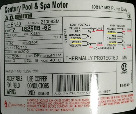
waterway spa pump motor 2 speed Century BN40 7-182688-02 ...

marathon motors wiring diagram - Wiring Diagram
115 230 Volt Century Electric Motor Wiring Diagram ...

Monochrome, Power Lines, Winlaton Mill, Tyne & Wear, England.

50 Century Ac Motor Wiring Diagram 230 Volts - Wiring ...

115 230 Volt Electric Motor Wiring Diagram - Wiring Diagram

115 230 Volt Electric Motor Wiring Diagram - Wiring Diagram

115 Volt Motor Wiring Diagram - wiring diagram

Century Ac Motor Wiring Diagram 115 230 Volts - Derslatnaback

49 Century Ac Motor Wiring Diagram 115 Volts - Wiring ...

2 HP 3450 RPM Air Compressor Electric Motor 115/230 Volts ...

33 Century Ac Motor Wiring Diagram 115 230 Volts - Diagram ...

I have a dayton 5k436j motor on a lathe, set up for 115 ...

Century Ac Motor Wiring Diagram 230 Volts - easywiring

45 Century Ac Motor Wiring Diagram 115 Volts - Wiring ...

115 230 Volt Century Electric Motor Wiring Diagram ...

Century Ac Motor Wiring Diagram 115 230 Volts | Free ...

Century Ac Motor Wiring Diagram 115 230 Volts Collection
115 230 Volt Century Electric Motor Wiring Diagram ...
115 Volt Ac Motor Wiring - Wiring Diagrams Thumbs - Baldor ...

115 Volt Motor Wiring Diagram - Database | Wiring Collection
Century Ac Motor Wiring Diagram 115 230 Volts Collection
Century Ac Motor Wiring Diagram 115 230 Volts - Diagram ...
33 Century Ac Motor Wiring Diagram 115 230 Volts - Wiring ...
40 Century Ac Motor Wiring Diagram 230 Volts - Wiring ...
Gould Century Motor Wiring Diagram - Cadician's Blog
115 Volt Motor Wiring Diagram - Wiring Diagrams Hubs ...

115 230 Volt Electric Motor Wiring Diagram - Wiring Diagram
![[DIAGRAM] Century Electric Motors Wiring Diagram 115 Volt ...](https://static-cdn.imageservice.cloud/13631081/93-geo-metro-radio-wiring-auto-electrical-wiring-diagram.gif)
[DIAGRAM] Century Electric Motors Wiring Diagram 115 Volt ...


Comments
Post a Comment