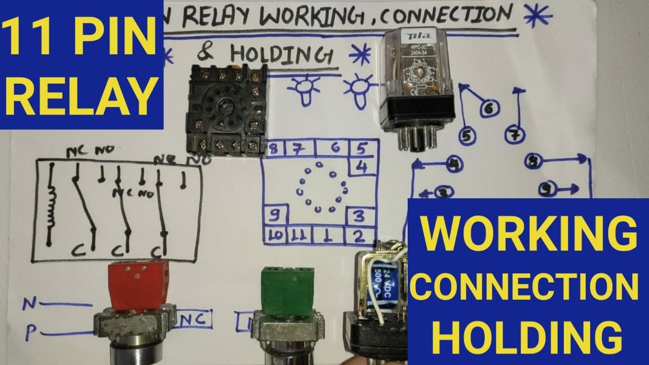
39 11 pin relay diagram
555 Timer IC-Block Diagram, Working, Pin Out Configuration, Data Sheet – A complete basic tutorial This article covers every basic aspect of 555 Timer IC. You may already know that SE/NE 555 is a Timer IC introduced by Signetics Corporation in 1970’s. 10.11.2016 · If you are using a relay board, as we are in this project, simply connect the digital I/O pins 4 and 5 of the Arduino to the input pins of the relay. If you are not using the relay board, the connections must be made as per the circuit diagram. Note: We need to be extremely careful when connecting AC Mains supply to the relay board.
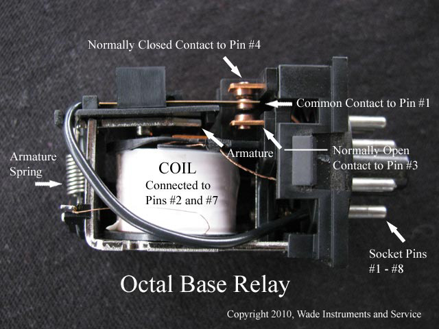
02.01.2015 · This diagram shows how another type of relay, the single pin/single throw (SPST) operates. It has a #30 pin (common) with two #87 pins (Normally Open) that are connected internally. This type of relay allows you to wire two systems …

11 pin relay diagram
This 12v battery charger circuit with Auto cut provides the Automatic cut off facility when the battery get fully charged. Before the use of this circuit you need to adjust the Cut off voltage range for autocut . This adjustment is done by the 10k preset , and a multimeter connected with the output terminals that goes to battery . 06.07.2018 · How to wire a 4 pin LED switch. Wiring a rocker switch depends on the type you plan on using, so your wiring will depend on the amount of pins your rocker switch has. 4 Pin LED switch wiring shouldn’t cause any headaches if you follow the right diagram. If you want to know how to wire a 4 pin LED switch, following instructions tailored for a ... 30.11.1994 · Main Fuse Box Diagram (up to 30.11.94) ... 11: Auxiliary fan relay, 1st and 2nd stage (K9) Air conditioning (automatic)/air conditioning (tempmatic) 7.5: Automatic air conditioning (AC) pushbutton control module: Air conditioning (tempmatic) pushbutton control module : 12: Stop lamp switch: 10 Stop lamp Trailer stop lamp Brake signal for ABS Brake signal for ASR Brake …
11 pin relay diagram. Feb 10, 2021 · Locations and descriptions of the fuses and relays of the under-hood fuse/relay box for 1996 Ford F150, F250 and F350 (gasoline engine only). The under-hood fuse/relay box is known as the Power Distribution Center in the Ford service/repair literature. Fuse box diagram (location and assignment of electrical fuses and relays) for Toyota RAV4 (XA30; 2006, 2007, 2008, 2009, 2010, 2011, 2012). The Arduino NANO is a smaller, breadboard-friendlier version of the Arduino UNO. This Arduino NANO Pinout diagram reference is a handy guide for using this board: Arduino NANO Pinout Description The Arduino NANO pins, similar to the UNO, is divided into digital pins, analog pins and power pins. The NANO has two more analog … Wiring diagrams include location information, wiring, pin identification, troubleshooting, maintenance, function descriptions, and more. This includes all information that follows wiring and wire connections. BMW E38, 7ser. 03/1994 to 09/1998 and 09/1998 BMW E39, 5ser. 12/1995 to 09/1998 and 09/1998 BMW E46, 3 ser. BMW E52, 8 ser. (Z8) BMW E53 E70, X5 ser. BMW …
25.04.2015 · Microcontroller pins usually provide a maximum current of 1-2 mA per pin which is not enough o operate relay. The circuits which are used to derive relays are called relay driver circuits. Therefore Relay driver circuits using ULN2003 are used to drive relays. There are many other ways to operate relays. I will also discuss other methods of relay driver circuits in the … Fuse box diagram (location and assignment of electrical fuses and relays) for GMC Sierra (mk4; 2014, 2015, 2016, 2017, 2018) The relay function can be better understood by explaining the following diagram given below. Relay Design. The diagram shows an inner section diagram of a relay. An iron core is surrounded by a control coil. As shown, the power source is given to the electromagnet through a control switch and through contacts to the load. 30.11.1994 · Main Fuse Box Diagram (up to 30.11.94) ... 11: Auxiliary fan relay, 1st and 2nd stage (K9) Air conditioning (automatic)/air conditioning (tempmatic) 7.5: Automatic air conditioning (AC) pushbutton control module: Air conditioning (tempmatic) pushbutton control module : 12: Stop lamp switch: 10 Stop lamp Trailer stop lamp Brake signal for ABS Brake signal for ASR Brake …
06.07.2018 · How to wire a 4 pin LED switch. Wiring a rocker switch depends on the type you plan on using, so your wiring will depend on the amount of pins your rocker switch has. 4 Pin LED switch wiring shouldn’t cause any headaches if you follow the right diagram. If you want to know how to wire a 4 pin LED switch, following instructions tailored for a ... This 12v battery charger circuit with Auto cut provides the Automatic cut off facility when the battery get fully charged. Before the use of this circuit you need to adjust the Cut off voltage range for autocut . This adjustment is done by the 10k preset , and a multimeter connected with the output terminals that goes to battery .
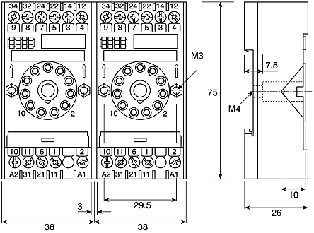
14 Pin Relay Wiring Diagram - Finder Relay Wiring ...

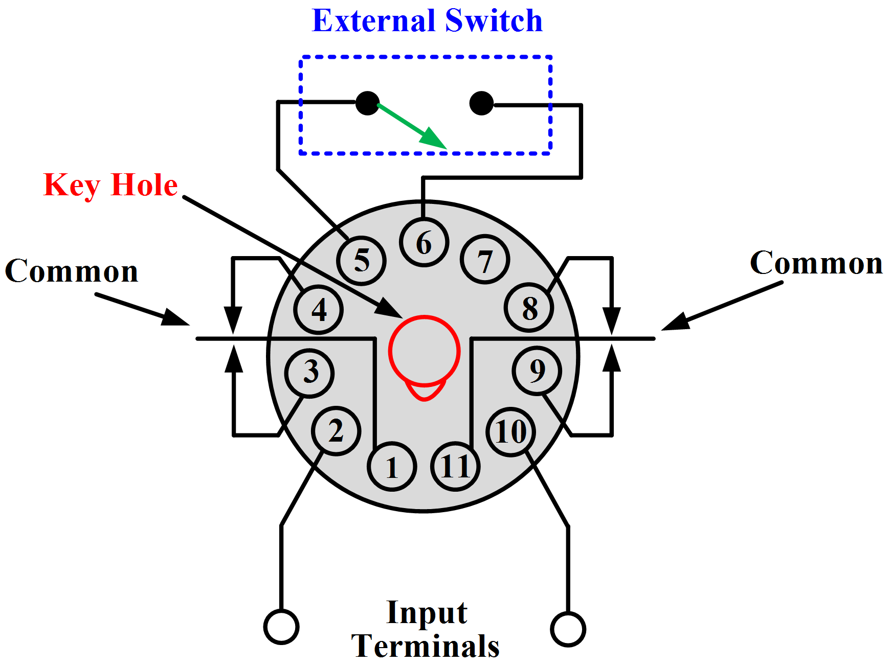
Wiring Diagram PDF: 11 Pin Relay Base Wiring Diagram

Wiring Manual PDF: 11 Pin Latching Relay Wiring Diagram

Wiring Diagram PDF: 11 Pin Relay Base Wiring Diagram

Wiring Diagram PDF: 11 Pin Relay Base Wiring Diagram

Wiring Octal 11-pin Latching Relay - CR4 Discussion Thread
11 Pin Relay Wiring Diagram Pdf 9 Images - Under Hood Fuse ...
Wiring Manual PDF: 11 Pin Cube Relay Wiring Diagram
Ice Cube Relay Wiring Diagram | Wiring Diagram

11 Pin Timing Relay Wiring Diagram - Wiring Diagram

Wiring Manual PDF: 11 Pin Cube Relay Wiring Diagram
Western 11 pin wiring diagram | The largest community for ...

Relay Base Wiring Diagram - Wiring Diagram And Schematic ...

11 Pin Relay Wiring Diagram Pdf 9 Images - Under Hood Fuse ...

Wiring Diagram PDF: 11 Pin Relay Socket Wiring Diagram

41 11 Pin Relay Diagram - Wiring Diagram Source Online

Wiring Manual PDF: 11 Pin Cube Relay Wiring Diagram

44 11 Pin Relay Base Diagram - Wiring Diagram Source Online

On July 24, 1969, President Richard Nixon welcomes the quarantined Apollo 11 astronauts, Neil Armstrong, Michael Collins, and Buzz Aldrin, aboard the U.S.S. Hornet after the historic Apollo 11 lunar landing mission.

44 11 Pin Relay Base Diagram - Wiring Diagram Source Online

people working outdoors on a Windows 11 device.

14 Pin Relay Wiring | Working | Base Wiring Diagram, Three ...

Wiring Diagram PDF: 11 Pin Timer Relay Wiring Diagram
Solid State Timer Wiring Diagram - Hanenhuusholli

Relay Wiring Diagram 11 Pin | Wiring Diagram
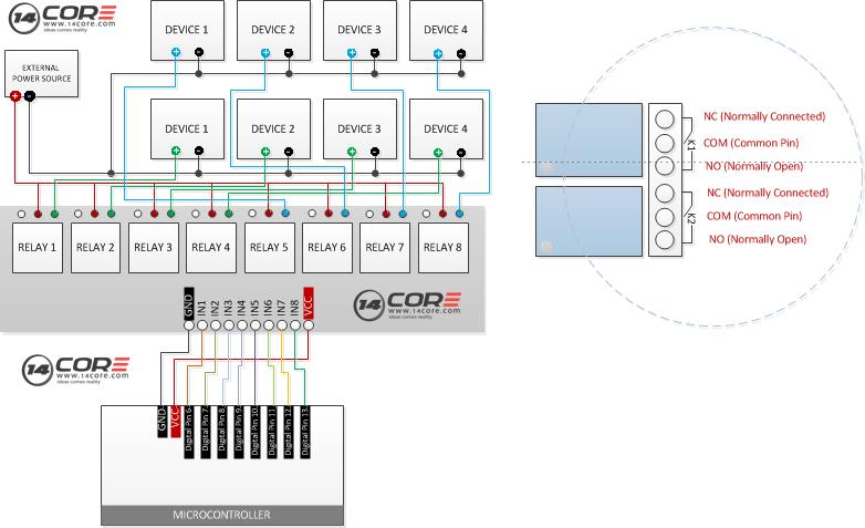
Wiring 8 Channel Optocoupler Relay Module | 14core.com
44 11 Pin Relay Base Diagram - Wiring Diagram Source Online
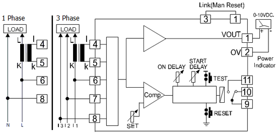
11 Pin Timer Relay Wiring Diagram - 6

36 11 Pin Relay Diagram - Wiring Diagram Online Source
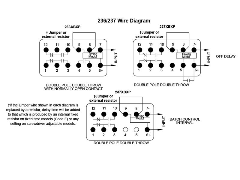
Wiring Diagram PDF: 11 Pin Timer Relay Wiring Diagram

Wiring Diagram For 11 Pin Relay - EZATYNAMAKU

49 Omron 11 Pin Relay Wiring Diagram - Wiring Diagram Plan
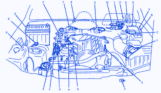
Suzuki Sidekick 1998 Front Engine Fuse Box/Block Circuit ...

41 11 Pin Relay Diagram - Wiring Diagram Source Online

person working on a Windows 11 tablet in home

Krpa 11ag 120 Wiring Diagram Collection | Wiring Collection

Relay Wiring Diagram 11 Pin | Wiring Diagram
Wiring Diagram For 11 Pin Relays - Wiring Diagram
S3-MP | Releco 11 pin Relay Socket, 250V ac for use with ...


Comments
Post a Comment