38 led load resistor wiring diagram
01-05-2019 · Hence, to design a 5-minute timer circuit, change the resistor value with 272.7 k ohm. And, after 5 Minute the LED will be turned ON. As soon as the Pin2 of 555 Timer IC is triggered, the timer will start timing and LED will be turned OFF. After 5 Min of time duration, pin3 of 555 Timer IC will again become low and the LED will be turned ON. Redraw the circuit diagram with the selected load resistor and be sure to include all voltage polarities and current directions. Any general purpose low power transistor can be. The diagrams below show how to connect an LDR light sensor to a transistor to make a light-sensitive circuit switch on an LED.
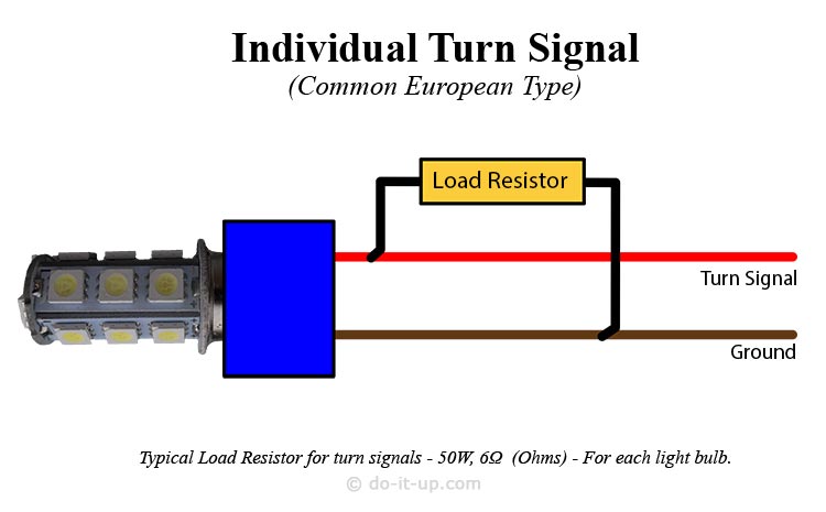
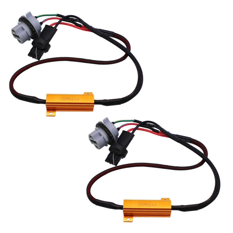
Load Resistors. Part No. LR12/2. 12 Volt 50 Watt 6Ω Ohms, Twin Blister. SOLR12/400mm. 12 Volt 50 Watt 6Ω Ohms, 400mm Cable, Single Bulk. LR24/2. 24 Volt 50 Watt 24Ω Ohms, Twin Blister. $29.98.
Led load resistor wiring diagram
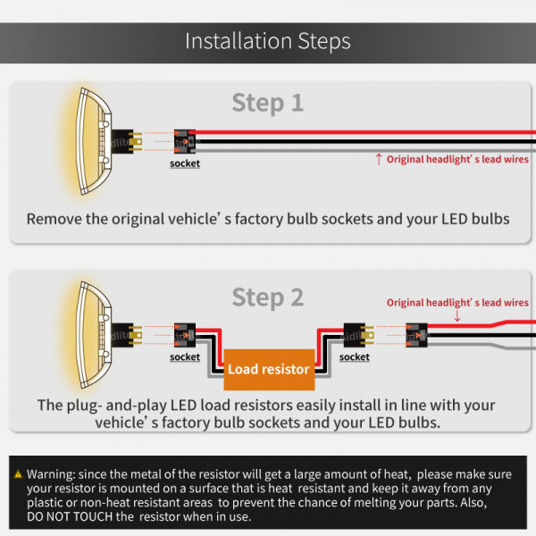
Always mount the load resistor to metal using zip-ties, not double-sided tape. In sum, 1) Merge the wire together instead of using T-tap to ensure perfect connection 2) Always try different combinations for double-filament bulbs (at most 3 combinations) 3) Mount the resistor to metal to prevent any heat damage. 04-11-2018 · Graphic 7d088 2005 Silverado Engine Diagram Digital Resources 2004 Gmc Truck Engine Diagram Car Engine Diagram 1995 Chevy 2010 Chevy Silverado 1500 Engine Diagram ... LED Resistor Wiring Diagrams: Calculating the Size of a Load Resistor: Buying LED Lights & Load Resistors: Precautions: Any installation is at your own risk. Each vehicle may be different, or may have been previously modified. Disconnect the battery, when wiring vehicles. If you're unsure, use a qualified auto electrician.
Led load resistor wiring diagram. Schematic diagram. Wiring diagram. Installation diagram. 2 - CONSTITUTION OF THE DIAGRAMS: Schematic diagram: supplies ( + and -) components (with references, function symbols and internal electro-mechanical details, except for electronics) connector sockets on components earth points wire lines (with reference) Wiring diagram: supplies (+ and -) Load resistors included, so I don't have hyperflash. Honestly don't care about the DRLs. I did install LED bulbs in the Suburban for the DRLs, and, of course, only one works. It's such a PITA to get to them, I'm not going to worry about it. Tried LED headlights on the Sierra, they started flickering after about six months. I've got HIDs in both ... Duet 3 Mainboard 6HC Wiring Diagram ... There is no flyback diode on this output, so if you connect a high-current inductive load, you must use an external flyback diode ... If connecting to a non MDIX enabled port use a crossover cable. Orange LED on Ethernet port indicates Ethernet enabled, green LED indicates network ... Diagram i found online for the resister install. The correct wires to tie into on the passenger side are the pink wire and the white wire with. The optional SYLVANIA load equalizer can be used to eliminate the hyper flash equalizer to a flat metal surface for proper heat transfer, then attach wires to. If hyper flashing is noticed, wire in one ...
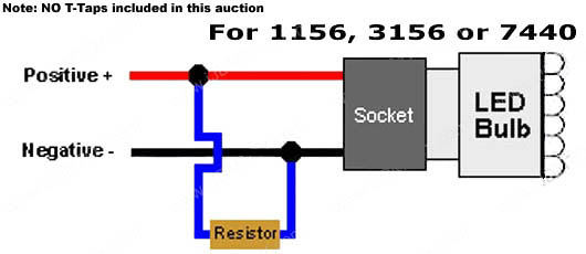
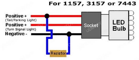
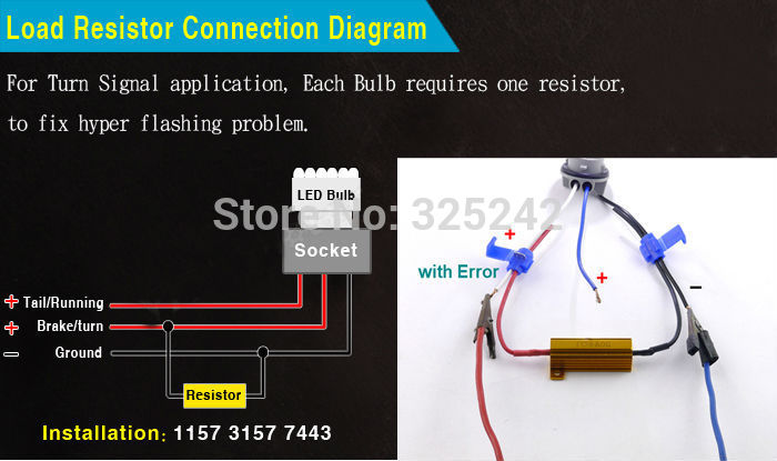
14 Posts. Discussion Starter · #11 · Aug 29, 2011. Just finished tracing the tail light wiring and and installing the resistor I purchased from superbrightleds.com Resistor gets warm, but has ZERO effect on the blink rate. I cant. believe Im the only owner to run across this issue. 09-04-2018 · I LED Driver Basics 1. 1 What is a LED Driver. Led driver changes the power supply to a specific voltage current to drive the LED voltage converter. In general, the input of the LED driver includes the high voltage power frequency AC (i.e., the city electricity), the low voltage DC, the high voltage DC, the low voltage and high-frequency AC (such as the output of the … If hyper flashing is noticed, wire in one load resistor into the right turn signal circuit and another the vehicle, which ever is easiest to access the wiring near. 3. It sounds like I need to attach one of the wires to the negative wire from the turn signal Do I need to wire the equalizer close to the new switchback led bulb or can I wire it ... LOAD RESISTOR INSTALLATION INSTRUCTIONS WARNING: Load Resistors are designed to get HOT! DO NOT Install on/near painted surfaces or plastic! LED Bulb Bulb Socket SPLICE HERE SPLICE HERE GROUND Wire (-) POWER Wire (+) Load Resistor Using the diagram below, splice the Load Resistor's wires in so that it connects ACROSS the positive and negative wires of the vehicle's TURN SIGNAL bulb wiring.
Load resistors should be your very last resort if you can't find a replacement LED flasher that will work with your vehicle. A replacement flasher has the added benefit of being plug-and-play, requiring no modification whatsoever to your vehicle or its wiring. Don't use a 50 watt resistor just because some guy on the Internet tells you to. I have added a diagram for you which details how to install the Putco LED Light Bulb Load-Resistors # DI34ZR. The LEDs will have one power wire and one ground wire; all you need to do is tap one end of the load resistor into the power wire and the other end will either ground to the trailer or the ground wire from the bulb. 12-06-2018 · No LED) Scion OEM style rocker switch wiring diagram. This switch also has a built-in LED that lights up when it’s in the on position, so if you’ve purchased one of these, below is a wiring diagram showing how you would go about wiring this particular rocker light switch, remember to pay careful attention to the markings on the pins: The wiring diagram is as per the pic below, thanks to Bareass Choppers that's where I found this, instead of using 2 resistors I just used 1 Narva LED load resistor wiring one end into the earth wire and connecting the other end to the two diodes and then to each of the indicator circuits. Attached Images.
do-it-up.com | » How to Install Load Resistors for LED Turn ...
Led load resistor wiring diagram load resistor instructions plasmaglow led productsled bulb bulb socket splice here splice here ground wire power wire load resistor using the diagram below splice the load resistors wires in so that it connects across the positive and negative wires of. Led Power Indicator Circuit For 230v 240v Ac Mains Single ...

L.E.D. Wiring Diagrams | Car Audio Forum | CarAudio.com
02-03-2017 · The load cell is connected with the HX711 Load cell Amplifier using four wires. These four wires are Red, Black, White, and Green/Blue. There may be a slight variation in the colors of wires from module to module. Below the connection details and diagram: RED Wire is connected to E+; BLACK Wire is connected to E-WHITE Wire is connected to A-
BMW LED Load Resistor - webBikeWorld
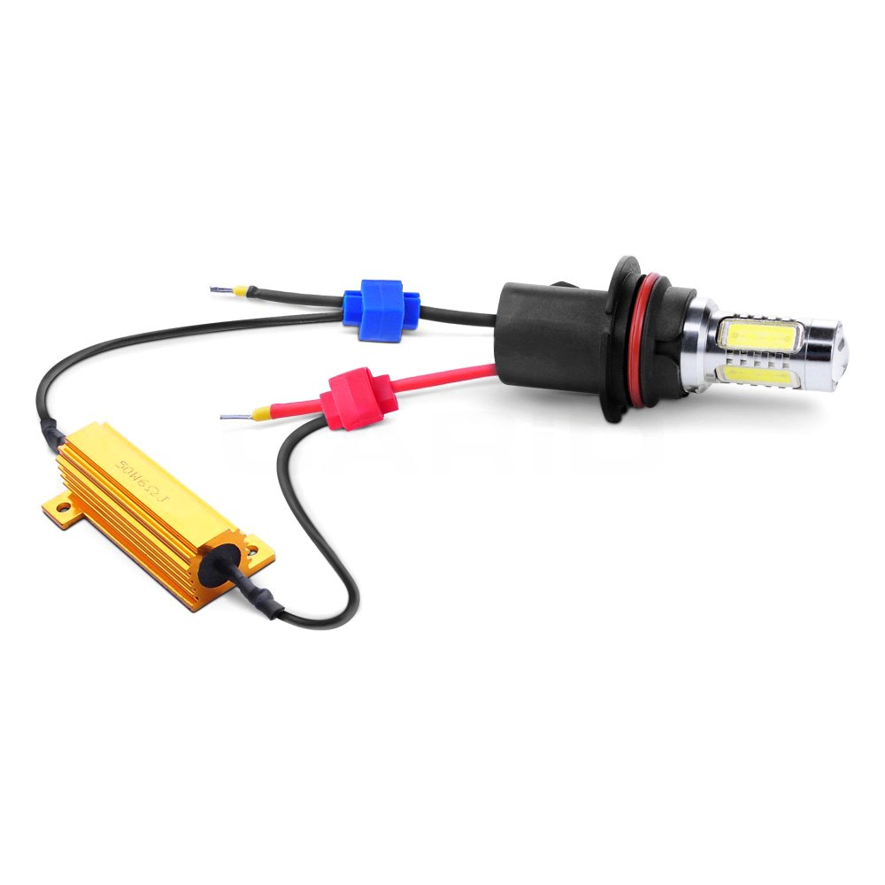
4.) Run the wiring and LED load resistor down to a suitable metal location, load resistors get hot, and adequate care must be followed when selecting a mounting location. Below is a picture of where I mounted the LED lead resistor on my truck. Note that I used both an aluminum heat sink, secured with 3M VHB 4622 industrial strength adhesive tape.
LED turn signal bulbs | Nissan Titan Forum
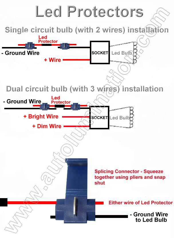
STEP 2: Using the enclosed quick connects, connect one end of the resistor to the power wire, and the other end of the resistor to the ground wire. See diagram The resistor can be installed in either direction. There is no concern about which end of the resistor is connected to power, and which to ground. Slip the quick connect onto the vehicle ...

ORACLE 3157 Switchback + Load Equalizer Kit
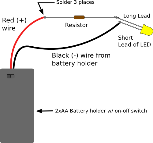
01-11-2013 · The resistor R1 controls the amount of current going through the LED. It’s simple to calculate. I have written an article on how to calculate the resistor value for an LED. If you are using an LED with 2V voltage drop, you will have a 7V voltage drop over the resistor when the transistor is ON. By using Ohm’s law we can find the current:
Lumen® DCDR50W6 - LED Load Resistors
This video shows which wires you need to connect your load resistor to in order to restore cruise control to your vehicle. This also corrects hyper flash tha...

Installing switchback/dual color LEDs for turn signals. Need ...
Led turn signal load resistor wiring diagram stop turn signal a typical load resistor for a 21 watt turn signal light bulb would have a rating of 50 watts 6 ohms. Slip the quick connect onto the vehicle. Also notice that the anode on the led is connected to positive. Load resistors should be your very last resort if you can t find a replacement ...
Help with LED load resistors / protectors - RX8Club.com
Creative Led Load Resistor Wiring Diagram Details About 4Pcs 50W 6Rj - Led Load Resistor Wiring Diagram. Wiring Diagram arrives with numerous easy to adhere to Wiring Diagram Guidelines. It is meant to aid each of the typical user in creating a proper method. These instructions will likely be easy to understand and implement.

Amazon.com: TUINCYN 4pcs 50W 8 ohm LED Load Resistors(DIY ...
If you need parts, try...LED Load Resistors (USA) - https://ebay.us/m8PKfzLED Load Resistors (UK) - https://ebay.us/uRD203LED Load Resistors (AUS) - https://...

Load Resistors For Autos and Motorcycle systems with LED Bulbs
Standard 3157 bulb / socket configuration / diagram. General LED load resistor information. LED Switchback Wiring Diagram. WK2 rear fog upgrade installation instructions WK2 Interior lift gate removal instructions Using T Taps WK2 Grand Cherokee Load Resistor Info
DIY: LED DRL/Turn Signal with resistor install | Toyota ...
Creative Led Load Resistor Wiring Diagram Details About 4Pcs 50W 6Rj - Led Load Resistor Wiring Diagram. Wiring Diagram arrives with numerous easy to adhere to Wiring Diagram Directions. It is meant to help each of the common consumer in developing a suitable method. These instructions will likely be easy to comprehend and apply.

4pcs 50W 8ohm LED Load Resistors Decoder for LED Turn Signal ...
Led Resistors Diagram - 8 images - horn24vdcspdt spdt 24vdc 40a horn relay technical data, ... LED Load Resistor. LED Resistor Wiring. LED Lamp Wiring Diagram. LED 5V Resistor. LED Light Emitting Diode. 12 Volt LED Resistor. 9V LED Circuit. LED Trailer Lights Diagram. Gallery of Led Resistors Diagram.
Basics: Picking Resistors for LEDs | Evil Mad Scientist ...
But I just looked over diagrams for 13-15 and can't seem to find anything for 12's.. They are Yellow and Red for turn and stop. A wire diagram is good for having a good idea of where to work. Always double check your wire colors with test light. The Load Resistor would go between the Turn Power wire and the Turns ground. It don't go inline James

4PCS 50W 12ohm 12RJ LED Load Resistor Decoder Fix Hyper Flash ...
Hopefully those looking for practical information on electrical circuits and wiring LED components found this guide first. It's likely though, you've already read the Wikipedia page about Series and parallel circuits here, maybe a few other Google search results on the subject and are still unclear or wanting more specific information as it pertains to LEDs.

H13 9008 LED Headlight Resistor Decoder|Lasfit Auto Lighting
A quick explanation of the resistors chosen: Assuming a nominal 12V supply, the 15Ohm resistor will allow a current of 0.8A. The power dissipated by the resistor will therefore = V*A = 12*0.8 = 9.6W, thus making the 10W rated resistor sufficient (particularly when installed with a means to transfer heat away).
2pcs Car Load Resistor Wiring Harness 7440 T20 50W 6ohm Load ...
Led Load Resistor Wiring Diagram - led autolamps load resistor wiring diagram, led load resistor wiring diagram, Every electric arrangement is composed of various distinct components. Each part ought to be placed and linked to other parts in specific way. Otherwise, the structure will not work as it should be.

Do I have this correct - Dodge Ram xBA Turn Signals ...
05-11-2021 · The diagram above outlines in the most simplistic terms, my camper van electrical design. Using the formula explained here, I calculated I’d need about 80 amp hours (ah) per day including contingency. Assuming the batteries are 50% efficient, I’d need to fit 160ah batteries.

High Power LED Load Resistors 25W
(2) 4157NA LEDs (2) resistors with male connectors installed (4) t-tap connectors (4) self tapping screws Comparison between stock 4157NA bulb and new LED Diagram i found online for the resister install. Will be a little different on the Tundra as the wire colors are different. There is a ground wire, DRL wire and turn signal wire.
7440 Switchback LED Turn Signal Light Bulb Installation Guide ...
Per Putco, you would need 1 load resistor inline with the wiring harness feeding LED bulb for a turn signal. I believe your Sierra has two bulbs per side, one for the running lamp, one for the brake/turn signal.

9006 9005 9012 H10 9145 LED Headlight Load Resistor Harness Anti-Flick
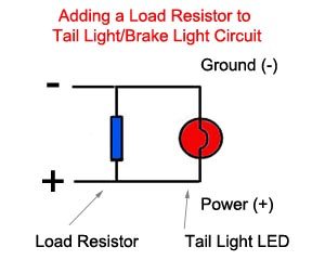
Multiple LED's Wiring Diagram. Notice that NO load resistor is needed. Also notice the Anode and Cathode connections. The Anode is the LONGER lead. The LEDs MUST be connected in series, NOT in parallel. NOTE: If using a light up switch connect the 3rd connection on the switch to ground. 12 LED's Wiring Diagram.
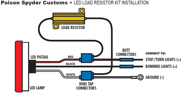
How to Install Poison Spyder LED Resistor Kit for LED Tail ...
16-07-2021 · 1. Limiting current resistor. If you use a load that uses constant current. For example, LED, Light bulbs, relay coil, and more. You can use a resistor in series with these loads. This way is cheapest and so easy. Suppose you have 6V 3W light bulbs. You can use a resistor. How to find resistor level. First, find the current of the light bulbs ...

How to Install Load Resistors for LED Turn Signal Lights : 6 ...
LED Resistor Wiring Diagrams: Calculating the Size of a Load Resistor: Buying LED Lights & Load Resistors: Precautions: Any installation is at your own risk. Each vehicle may be different, or may have been previously modified. Disconnect the battery, when wiring vehicles. If you're unsure, use a qualified auto electrician.
How to Install Load Resistors for LED Turn Signal Lights : 6 ...
04-11-2018 · Graphic 7d088 2005 Silverado Engine Diagram Digital Resources 2004 Gmc Truck Engine Diagram Car Engine Diagram 1995 Chevy 2010 Chevy Silverado 1500 Engine Diagram ...

do-it-up.com | » How to Install Load Resistors for LED Turn ...
Always mount the load resistor to metal using zip-ties, not double-sided tape. In sum, 1) Merge the wire together instead of using T-tap to ensure perfect connection 2) Always try different combinations for double-filament bulbs (at most 3 combinations) 3) Mount the resistor to metal to prevent any heat damage.
Wiring diagram for resistors to correct the flash rate ...

LED Blinker How-To (SV650) | Suzuki SV650 Riders Forum
How to Install Load Resistors for LED Turn Signal Lights : 6 ...

How to wire load resistors for LED turn signals? - HIDRetrofitKit
Load Resistor - Decoder for LED Headlight Bulbs - 9007 HB5

LED Resistor Kit (for JK LED Taillights) | Jeep Wrangler JK ...
Load resistor wiring help for turn signals | Impala Forums

how to wire in load resistor? | Page 2 | Yamaha Starbike Forum
Turn Signal Light 50W 6-Ohm LED Load Resistor Installation ...

LED Autolamps LR12/2 Load Resistor - 12V, 6 Ohms (Twin Blister)

4PCS 50W 12ohm 12RJ LED Load Resistor Decoder Fix Hyper Flash Turn Signal Lights-buy at a low prices on Joom e-commerce platform

2pcs H7 LED DRL Fog Light Canbus 50W 6Ohm Load Resistor ...

50 Watt 6 Ohm Resistor Kit for LED Taillights.
Park/Turn Led Switchback - Glass, Lighting, Mirrors, Sun ...


Comments
Post a Comment