43 gear free body diagram
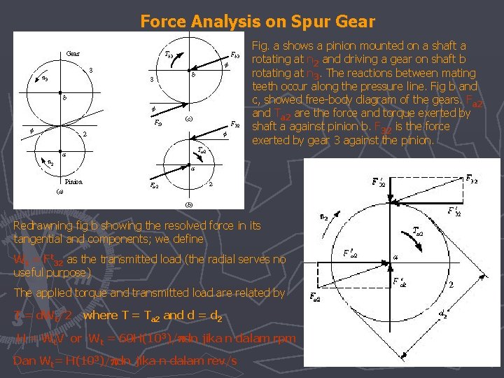
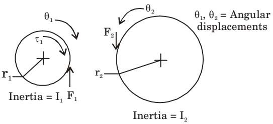
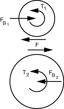
The free body diagram of the landing gear member which we got shows us that the reactions calculated for the members through analytical approach and the software validation is done The main landing gear structure which carries load is connected to the wing through lug joint The design of the maximum load carrying lug ... Draw the free body diagrams of the two spur gears shown in Figure P3.15. Use the resulting equations of motion to show that T 2 = NT 1 if the gear inertias are negligible or if there is zero acceleration. Here T 2 is taken to be the torque felt on shaft 2 due to the applied torque T 1.
The layout of a single planetary gear set and its free body diagram is shown Figure 1, where N, r, T, and w represent the teeth number, radius, torque, and angular velocity of gear, respectively ...
Gear free body diagram
Basic static equilibrium examples that emphasize drawing the free body diagram, choosing an axis, and evaluating torque without bothering to work out the num... This is shown in the free body diagram below: Figure 3 Wr Wt Wr Wt Tin Tin = 2(WT)(r) 20. 20 Due to the fact that no other radial or transverse loadings exist, we used the gear weight as a force in the analysis of Shaft 1. •Free Body Diagram M F f k f M k F x M •Where and are force applied by the spring and inertial force respectively. f M. Example-1 16 •Then the differential equation of the system is:F kx Mx •Taking the Laplace Transform of both sides and ignoring ... Gear •Gear is a toothed ...
Gear free body diagram. Free body diagram (FBD), machine design, statics, and animated GIF. Free body diagrams of mechanical systems A free body diagram (FBD) is a graphic representation of a body (element or segment of an element, sub-assembly, or assembly) in which all connecting bodies have been removed, or the body diagram Figure 4: Planet gear free body diagram. We can also write Newton's Second Law (in translational form) in the direction of the three forces shown above (aligning the y-axis with that direction): The linear acceleration, , can be replaced by to yield: (5) Planet Carrier Let's look at the idler gear forces (not a free body diagram). Looking at the diagram above, there is a net zero axial force on the shaft. Just because the net axial force is zero does not mean we should ignore the axial forces! Different types Of Chassis Used in Automobile vehicles. Automobile Chassis Components and Drive System. Types Of Automobile Bodies and Requirement of Automobile Body. Classification Or Types of Automobiles with examples. Differential gear Box – Diagram, parts, Types, Working, Advantages. Automobile Rear Axle types- Live and Dead Axis. Front ...
2, therefore gear 1 is called the driver and the gear 2 is called the driven or follower. It may be noted that the motion of the driven gear is opposite to the motion of driving gear. (a)(b)(c) Fig. 13.1. Simple gear train. Let N1 = Speed of gear 1(or driver) in r.p.m., N2 = Speed of gear 2 (or driven or follower) in r.p.m., Without a properly operating clutch, power transfer and gear shifting would be very difficult. The clutch is located between the engine flywheel and the transmission. It is often housed within the bellhousing to protect it from external contaminants. Much older vehicles had more of a fully open design. The first section of this system starts at the flywheel. Connected to the flywheel is the ... 1.2 Free Body Diagram of Complete Epicyclic Gear Train Fig- 2 shows the free body diagram of complete epicyclic gear train in which the input torque is applied to the sun gear and this torque is resolve into two component namely tangential force and radial force. In which the tangential force causes bending stresses on the gear tooth and radial gear box, power is lost through friction and the power output is smaller than the power input. The efficiency is defined as: 1 1 2 2 1 1 2 2 N T N T 2π N T x 60 2π N T x 60 Power In Power Out η= = = Because the torque in and out is different, a gear box has to be clamped in order to stop the case or body rotating.
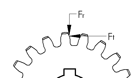
Search by diagram to shop for parts for your vintage Jeep restoration. Our clickable, exploded diagrams make it easy to find the part you need. FREE SHIPPING ON ONLINE ORDERS OVER $98.00 See Details. 1-888-648-4923 Mon-Fri, 9AM-5PM EST. Tech Guides. See All; 41-45 GPW ; 41-45 WILLYS MB ; 46-49 WILLYS CJ-2A ; 49-53 WILLYS CJ-3A ; 53-64 WILLYS CJ-3B ; 50-52 WILLYS M38 ; 52-71 … FIGURE 47: Free Body Diagram of The Conservative Loading System for The Nose Landing Gear 98 FIGURE 48: Reaction Forces Assessment of Z-Direction (A); Y-Direction (B); X-Direction (C) 101 FIGURE 49: Front View (A) and Side View (B) of 5% Model's Deformation on Displacement 102 FIGURE 50: Stress (A) and Deformation (B) of Shock Strut Assembly 104 Gear Technical Reference. >. Gear Forces. When the gear mesh transmits power, forces act on the gear teeth. As shown in Figure 12.1, if the Z-axis of the orthogonal 3-axes denotes the gear shaft, forces are defined as follows: The force that acts in the X-axis direction is defined as the tangential force Ft (N) The force that acts in the Y-axis ... A gear is a rotating circular machine part having cut teeth or, in the case of a cogwheel or gearwheel, inserted teeth (called cogs), which mesh with another (compatible) toothed part to transmit (convert) torque and speed. The basic principle behind the operation of gears is analogous to the basic principle of levers. A gear may also be known informally as a cog.
Solved Pinion 2 In Fig 13 34 A Runs At 1750 Rev Min And Transmits 2 5 Kw 1 Answer Transtutors
Figure 6. Dynamic model of a landing gear strut with the free body diagram 24 Figure 7. Points of interest dynamically applied to a linear strut 24 Figure 8. Depiction of geometric components used in determined strut length 24 Figure 9. Dynamic model of a landing gear with insufficient tire force 39 Figure 10.

Free Body Diagram An Overview Sciencedirect Topics
15.10.2019 · How to get all Witcher 3 Feline gear - also known as the Witcher 3 Cat gear - to get the Feline Sword and Feline Armor, including Enhanced, Superior, Mastercrafted and …

Free Body Diagram Of Two Gear Download Scientific Diagram
If the 15-tooth gear is the driving gear and the 30-teeth gear is the driven gear, their velocity ratio is 2. Other examples of gears are in simdesign/gear10.30.sim and simdesign/gear20.30.sim 7.3.1 Generation of the Involute Curve. Figure 7-3 Involute curve. The curve most commonly used for gear-tooth profiles is the involute of a circle.
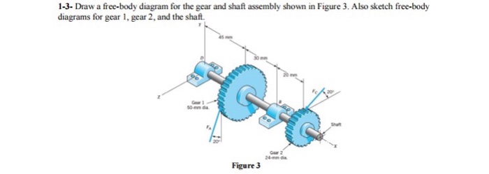
Solved Draw A Free Body Diagram For The Gear And Shaft Chegg Com
Basic Gear Mechanisms: Cars, clocks, and can openers, along with many other devices, use gears in their mechanisms to transmit power through rotation. Gears are a type of circular mechanical device with teeth that mesh to transmit rotation across axes, and they are a very…
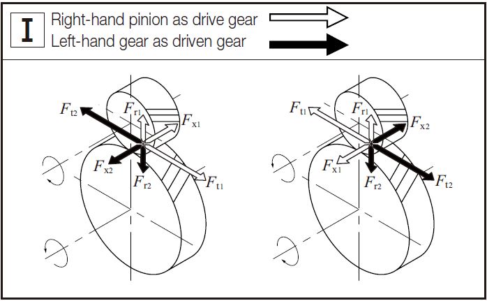
Gear Forces Khk Gear Manufacturer
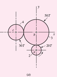
Gear 4, which is driving the second pair of gears in the train has normal diametral pitch of 5 teeth/in, 15 teeth and a normal pressure angle of 20°and is cut left handed with a helix angle of 15°. Mating gear 5 has 45 teeth. Find the magnitude and direction of the force exerted by bearings C and D on shaft b if bearing C can take only radial load while bearing D is mounted to take both ...
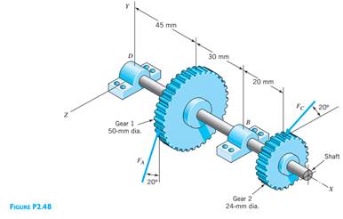
Solved Draw A Free Body Diagram For The Gear And Shaft Assembly Shown In 1 Answer Transtutors
Example 8 : A system with two blocks, an inclined plane and a pulley. A) free body diagram for block m 1 (left of figure below) 1) The weight W1 exerted by the earth on the box. 2) The normal force N. 3) The force of friction Fk. 4) The tension force T exerted by the string on the block m1. B) free body diagram of block m 2 (right of figure below)

A7apendice4
Hub gear systems generally have a long and largely maintenance-free life though some are not suitable for high-stress use in competitions or hilly, off-road conditions. Many commuter or urban cycles such as European city bikes are now commonly fitted with 7-speed gear-hubs and 8-speed systems are becoming increasingly available. Older or less costly utility bicycles often use 3-speed gear-hubs ...
Force Analysis Spur Gears Equation And Calculator Engineering Reference And Online Tools
26.11.2021 · Triumph Spitfire 4 MK1, (1964), Plus original Engine, Rear diff and 2 x four speed Gear box's. Spitfire 4 MK1 ( 1964 ). Yep that’s right, she is a MK1 ( 1964 ), a very rare 1. I fitted but only after a complete engine rebuild a 1500 engine, Overdrive Gear Box and the associated Rear Diff to match, so she runs smooth and easy without revving her ass off at 50 MPH.

Pdf Free Body Diagrams With Animated Gif Files Semantic Scholar
Free-body diagrams of the isolated component parts of the tripod landing gear, together with the notation for unknown reactions and internal forces and .... Solution for C44. Draw the free-body diagram of the wheel and member ABC used as part of the landing gear on a jet plane. The hydraulic cylinder AD acts as ....

Free Body Diagram Of Two Gear Download Scientific Diagram
Vw t5 gear linkage diagram. Gear lever repair kit for Volkswagen Transporter T5 Transporter T5 Van (7HA, 7HH, 7EA, 7EH) from 04/2003 MY Transporter T5 Minibus (7HB, 7HJ, 7EB, 7EJ, 7EF, 7EG, 7HF, 7EC) from 04/2003 MY Transporter T5 Platform / Chassis (7JD, 7JE, 7JL, 7JY, 7JZ, 7FD) from 04/2003 MYVolkswagen Vanagon Shift Linkage - Solid Wood Shift Knobs.

Free Body Diagrams Of Pinion And Gear Adapala S Forum
Example Problem 12-3: Strength of Gear Teeth P N RAO 16 − Gear: Sn = .5 (88 ksi) = 44 ksi (Table 12-1) Y = .421 Fs = 44,000 (1) .421 8 Fs = 2316 lb − Use F s = 1900 lb for design purposes. Example Problem 12-3: Strength of Gear Teeth (cont'd.) P N RAO 17 Classes of Gears • Transmitted load depends on the accuracy of the gears • Gear ...
Gear Asas Gear Jenisjenis Gear Spur Gears Have
Download scientific diagram | FREE BODY DIAGRAM OF SINGLE PLANETARY GEAR SET virtual work. Thus, the virtual work of the system in a virtual displacement is δW = T S δα + T C δβ + T R δθ.
A Pinion With Radius R1 And Inertia I1 Is Driving A Gear
Free Body Diagram Spur Gear System. Gear B is an idler and it transmits torque it receives from gear A and the gear C. The tangential component of force between gears A, B and C must equal to the tangential component of force between gears A and B. Therefore, the two radial components of forces acting on the gear B are equal as F r = F t tanφ.

Friction
The free body diagram is shown in Figure 2.5 iv) The resultant force on the shaft carrying Gear B; N FB FtA FrA 943.10 2 488.92 177.95 2 2 2 Figure 2.5 Spur Gear force directions for Problem 6 Problem 7 Based on the gear arrangement shown in Figure 2.2, and for an input power of 4.25 kW,
Ijret Org
A free body diagram shows all of the forces acting on an object, even if their effects are balanced out by another force. We will use free body diagrams to consider different situations involving the lamp that you find at your lab station (Figure 3.1). One force that always acts on the lamp is gravity.
1
A free body diagram is basically a sketch or drawing of the selected system consisting of a body, a portion of a body or a collection of interconnected bodies completely isolated or free from all other bodies, showing the interaction of all other bodies by forces on the one being considered.
Den Hartog S Mechanics
The gear calculator is a comprehensive software which, after inputting various parameters related to gear calculations, computes on-line automatically gear sizes, strengths, working forces, tooth forms, backlash conversions, etc. Because gear calculations require many complex formulas related to strengths and sizes, traditional gear design ...
How To Easily Calculate Tooth Forces On Spur And Helical Gears Mentored Engineer
Free Body Diagram Questions and Answers. Get help with your Free body diagram homework. Access the answers to hundreds of Free body diagram questions that are explained in a way that's easy for ...

Me 302 Dynamics Of Machinery Ppt Video Online Download
Looking at the free body diagrams for each gear, there is a normal force acting on each gear. The normal force acts at an angle from tangent called the pressure angle, Φ. In the case of the two gear set-up, there are opposing torques as well. For idler gears, there is no torque, but the normal forces from all gear meshes balance out.
Bordersengineering Com
Explain how a matrix equation is modeling the force and torque balance on one rigid body gear consisting of two gears molded together. Work out an analogous matrix for another gear body whose free body diagram is given. Write a linear equation that describes the torque balance due to the gear attached to the motor.
Gear Force Analysis Gear Forces In Spur And Helical Gears
We start by drawing free body diagrams with a contact force where the gears meet. The contact force is tangent to both gears and so produces a torque that is equal to the radius times the force. We can do a torque balance on each of the two gears ... (up on gear 1, down on gear 2). Example: Equations of motion for a system with gears.
Gearload Manual
•Free Body Diagram M F f k f M k F x M •Where and are force applied by the spring and inertial force respectively. f M. Example-1 16 •Then the differential equation of the system is:F kx Mx •Taking the Laplace Transform of both sides and ignoring ... Gear •Gear is a toothed ...

Gear Force Components Example 2 Bevel Gears Youtube
This is shown in the free body diagram below: Figure 3 Wr Wt Wr Wt Tin Tin = 2(WT)(r) 20. 20 Due to the fact that no other radial or transverse loadings exist, we used the gear weight as a force in the analysis of Shaft 1.

A Virtual Tool For Computer Aided Analysis Of Spur Gears With Asymmetric Teeth Intechopen
Basic static equilibrium examples that emphasize drawing the free body diagram, choosing an axis, and evaluating torque without bothering to work out the num...

Derive The Governing Equation For The Above Must Show Free Body Diagrams And Each Step Consider Homeworklib

A Shaft That Carries Gear 2 And 3 Is Supported By Two Bearings At B And D Gear 4 Is The Driver G Homeworklib

Gear Forces And Strength Durability Of Gears Sdpsi

Experiment 11 Gearing Ppt Video Online Download

Gear Forces And Strength Durability Of Gears Sdpsi
Journals Sagepub Com
Faculty Mercer Edu

Pdf Free Body Diagrams With Animated Gif Files Semantic Scholar

Force Analysis In Spur Gears Gear Force Analysis Assignment Help

Gear Forces And Strength Durability Of Gears Sdpsi

Helical Gear Forces Engineering Vortarus Technologies Llc

Free Body Diagram Of Two Gear Download Scientific Diagram

Eml 3004 C Problem 4 4 Page 138
Eis Hu Edu Jo

Me 302 Dynamics Of Machinery Ppt Video Online Download
Peer Asee Org

Seek And Geek Week 6 Bicycle Chain And Gears Oropeza
Gearload Manual
Staff City Ac Uk


Comments
Post a Comment