42 accelerator pedal position sensor wiring diagram
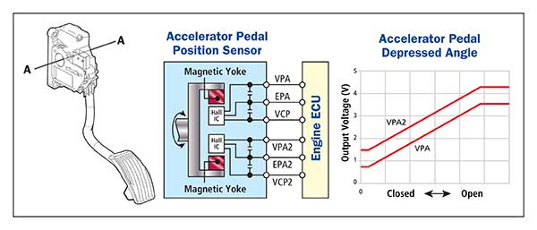
Accelerator position sensor diagram and its connections to the ECU. Innovative Circuits to Detect Faults in Accelerator. Pedal Sensor Wires in Modern Vehicles. Accelerator Pedal Actuator / Accelerator Pedal Position Sensor: Q: 40 '11-'13: 4-Wheel Active Steer (4WAS) Front Control Unit: Relay: R1: 5.6L VK56VD: Injector (No.1) R2: Shift Lock: R3: Intelligent Cruise Control (ICC) Brake Hold: R4: Front Wiper Reverse: R5: Cooling Fan (No.1) R6: Variable Valve Event and Lift (VVEL) Actuator Motor: R7 ...
How to perform the test · Use the vehicle circuit diagram to identify the two signal circuits from the sensor. · Connect PicoScope Channel A. · Minimize the help ...

Accelerator pedal position sensor wiring diagram
1992 Cadillac Seville - Where is the obd connector on the 1992 seville- question about Cars & Trucks ... control system inputs and outputs Basic Electrical Wiring, Electrical Circuit Diagram, Mécanicien ... Sensor TPS y sus fallas | Lapps.es Portal Mécanica. WHAT IS APP? · SENSOR LOCATION: · HOW TO TEST : · WIRING DIAGRAM : · WIRING TECHNICAL DATA: · TECHNICAL SPECIFICATION: · Accelerator Pedal Released Position Learning.
Accelerator pedal position sensor wiring diagram. Throttle Position Sensor. The MegaSquirt ® controller uses the throttle position sensor (TPS) to determine when the engine is at or near full throttle (to shut off feedback from the O2 sensor), when the engine throttle is opening or closing rapidly (and needing an accel/decel enrichment), and when the engine is flooded and needs to be cleared ... 6 Pin Accelerator Pedal Position Sensor Wiring Dia... Draw Wiring Diagrams - Software To Draw General Wi... Bush Plane Engine Diagram - What Materials Are Pla... Cherokee 1988 Electric Diagram : 1988 Jeep Wiring ... Panel Networking Admin Interface Guide / Network D... Car is a 2004 Volvo S80, 2.5L Turbo, FWD So in my [previous post here](https://www.reddit.com/r/MechanicAdvice/comments/ey1mnx/volvo_reduced_engine_performance_issue_even_after/) I was having trouble figuring out why my car is stuck in limp mode. Since then, I've checked it out with VIDA, and discovered that the P2126 /P2127 error is actually a result from an issue surrounding the Accelerator Pedal Position Sensor. I've got PDFs of the reports [here.](https://drive.google.com/folderview?... **GENERIC WARNING:** This guide is how I installed a WOT Box on my MZR 2.5. Your mileage may vary by model year, engine production series, production location, etc. As such, I am not responsible for any damages as a result of this guide. You assume all responsibility for all modifications and any resulting damages from improper installation, regular use, or just plain idiocy. This mod will dump fuel into the exhaust, so there is an increased risk for fire/destroying emissions components or roast...
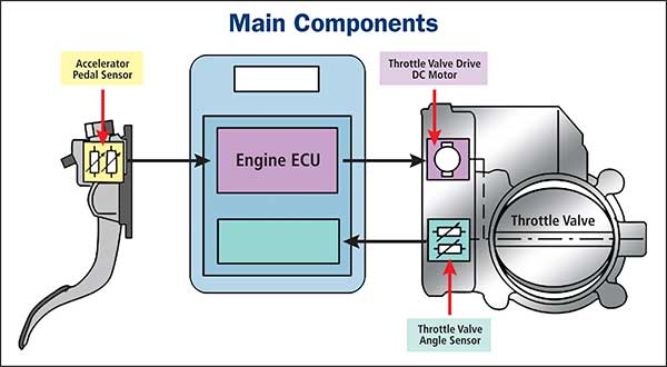
Accelerator Pedal Actuator / Accelerator Pedal Position Sensor: Q: 40 '11-'13: 4-Wheel Active Steer (4WAS) Front Control Unit: Relay: R1: 5.6L VK56VD: Injector (No.1) R2: Shift Lock: R3: Intelligent Cruise Control (ICC) Brake Hold: R4: Front Wiper Reverse: R5: Cooling Fan (No.1) R6: Variable Valve Event and Lift (VVEL) Actuator Motor: R7 ... The ECTS is responsible for controlling the throttle valve opening. When the accelerator pedal is pressed, the accelerator pedal position (APP) sensor sends a signal to the PCM indicating how much power the engine needs to produce. The PCM then commands the throttle plate to open accordingly. Hey everyone! Dunno if you guys can help out or not but.. Got a real good one here... Have a 1jzgte vvti out of a jzx171/jzs161 either way same motor/ecu. This motor has a single butterfly etcs-i setup (unlike the early dual butterflys) and is a 5 plug setup. Motor is in an s14 chassis (which is in theory irrelevant) Using wilbo666's diagrams/pinouts we have successfully got power and ground to ecu and can get the motor to fire but runs like absolute trash. Zero throttle response at all... 35 2010 kia soul 2.0 belt diagram; 37 accelerator pedal position sensor wiring diagram; 40 mack fuse panel diagram; 35 yamaha warrior 350 wiring diagram; 39 land pride finish mower belt diagram; 35 2003 mercedes c230 kompressor fuse panel diagram; 40 2002 jeep grand cherokee wiring diagram; 37 ford f350 suspension diagram; 38 chevy equinox ...
Joined: Jun 2016. RE: Throttle Position Sensor Problems - Solving them. I was taught that all wire repairs should be soldered with a linesman's knot and heat shrinked at a minimum, with adhesive heat shrink used on exterior connections. Butt connectors should be used just to get you from point A to B for a proper repair. Eautorepair.net redraws factory wiring diagrams in color and includes the component, splice and ground locations right in their diagrams. That saves a lot of time because you don't have to refer back to the component locator or circuit locations. Alldatadiy.com, on the other hand, uses the factory diagrams. The throttle position sensor is in the throttle, not at the pedal. At the pedal is the accelerator pedal position sensors. A lot of times it is a faulty throttle housing. Just be sure the wiring from the DME to the throttle housing is OK, as it has often been faulty when I tested it. - Nick at Pelican Parts bmw service documentation & wiring diagram Workshop manual BMW 1990-2008 (TIS ETK WDS ETM100) Replacing the battery in the key BMW E60, E90, E70, E87, E92, E63, E71 Bmw dme relay BMW 5-Series - fuse box diagram - DDE main relay - M57 DDE relay (K6300) M54. 11,221. 15 Accelerator Pedal Position (Pedalwertgeber - PWG). First of all, it is ...
Nissan Accelerator Pedal Position App Sensor Erwin Salarda
Starter Wiring Foxbody Ls Swap Ls1tech Camaro And P2138 is a diagnostic trouble code (DTC) for "Throttle/Pedal Position Sensor/Switch D/E Voltage Correlation". This can happen for multiple reasons and a mechanic needs to diagnose the specific cause for this code to be triggered in your situation. Flux Capacitor Perhaps Mustang Evolution Forum
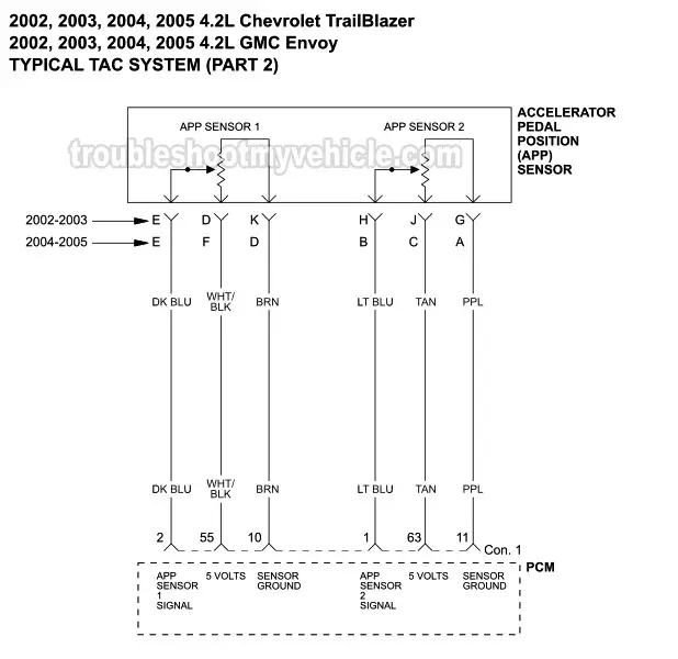
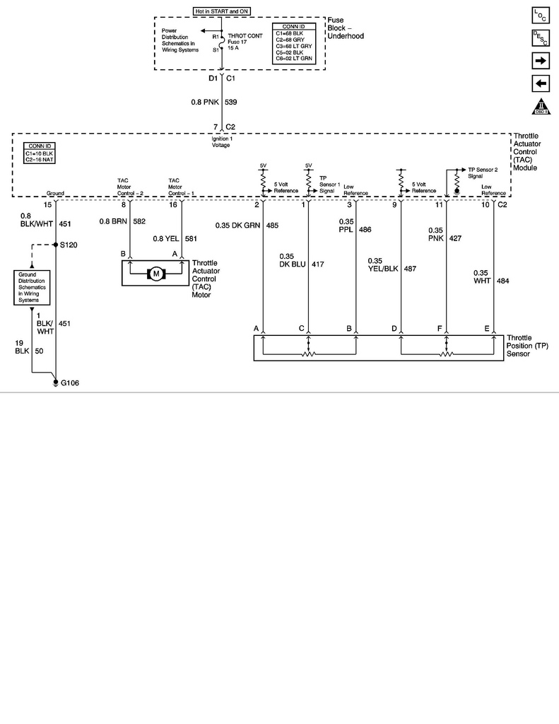
Part 1 Tac System Wiring Diagram 2002 2005 4 2l Chevrolet Trailblazer
The throttle system includes the throttle body, accelerator pedal, and the wirings between them. The electronic throttle control system control and monitors the position of the throttle. While older vehicles use a cable that's linked directly to the throttle body , most modern cars accomplish this feat through sensors and your vehicle's ECM.
I Have A P2127 Code Throttle Pedal Position Sensor Switch E
Throttle bodies come in several shapes, sizes and configurations and can. Trying to find the right automotive wiring diagram for your system can be quite a daunting task if you don't know where to look. Bosch Accelerator Pedal Position Sensor from www.efisolutions.com.au

Infiniti G35 V35 Manual Part 430
Automotive Electronic Diagnostics (Course-1) Located at 629.254 CON - With the ever increasing electronic content in today's vehicles, the need to be able to read automotive wiring diagrams is as important as knowing how to use the different equipments needed to perform diagnostic work. Reading wiring diagrams requires a bit of knowledge of electricity and experience.
Nissan Accelerator Pedal Position App Sensor Erwin Salarda
If the "Accelerator Pedal Position [%]" is based on the Voltage output from the variable resistor, then when in Cruise the Voltage will be fixed at the idle Voltage except if the driver presses it down again. (In contrast, the "Throttle Opening Angle [%]" is probably the Throttle Position Sensor signal which corresponds to the throttle plate ...
Testing Accelerator Pedal Position Sensors Aps
39 diagram of a hurricane with labels. Sara Haynes Blackwood · 2015 · Education... type of natural disaster is most likely to occur ( hurricane , tornado, earthq… Written By Christine J. Bell. Sunday, December 5, 2021 Add Comment Edit. 39 baseball field diagram with positions.
Dodge Ram Truck 1500 2500 3500 Manual Part 803
Fuses and relays Volvo XC90 (C; 2002 - 2014) 12.11.2021. The first generation of the luxury crossover Volvo XC90 was presented in 2002. Together with the S60, V70 and S80 models, it is built on the P2 platform. For its time, it became the largest among the crossovers produced by the company. In this material, we will analyze in detail the fuse ...

Nissan Almera Tino V10 Instruction Page 376
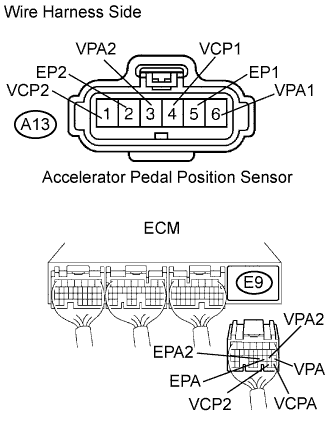
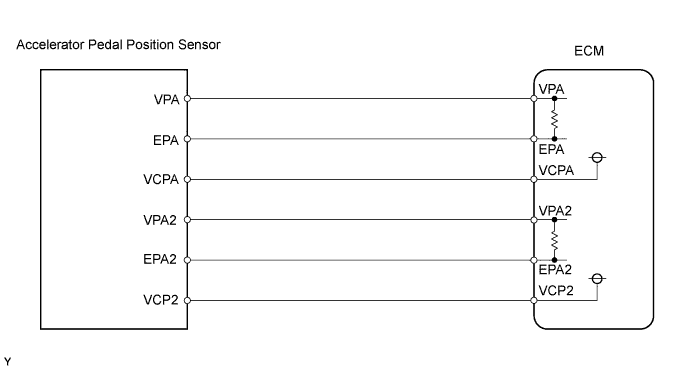
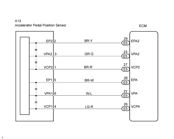
Throttle / Pedal Position Sensor / Switch "D" Circuit High Input - APP sensor - Open in EPA circuit - ECM. Comes on. DTC stored. ES-293. P2125. Throttle / Pedal Position Sensor / Switch "E" Circuit - APP sensor - ECM. Comes on. DTC stored. ES-293. P2127. Throttle / Pedal Position Sensor / Switch "E" Circuit Low Input - APP sensor - Open in VCP2 ...

Spn 974 Fmi 4 Fault Code 134 Blog Teknisi
Hey everyone! Dunno if you guys can help out or not but.. Got a real good one here... Have a 1jzgte vvti out of a jzx171/jzs161 either way same motor/ecu. This motor has a single butterfly etcs-i setup (unlike the early dual butterflys) and is a 5 plug setup. Motor is in an s14 chassis (which is in theory irrelevant) Using wilbo666's diagrams/pinouts we have successfully got power and ground to ecu and can get the motor to fire but runs like absolute trash. Zero throttle response at all unl...
Chrysler 300 300 Touring 300c Dodge Magnum Manual Part 1417
When the ignition SW is turned on and the brake pedal is pressed (Stop lamp SW on), if the stop light circuit is open, the current flowing from TERMINAL 7 of the light failure sensor to TERMINALS 1, 2 changes, so the light failure sensor detects the disconnection and the warning circuit of the light failure sensor is activated.
1996 1998 Throttle Position Sensor Circuit Diagram 1 6l Civic
Additionally, the Cat C16 7CZ engine wiring diagrams are included in high resolution PDF format. This is a complete OEM reference for professional mechanics to service and repair the engine. ... Accelerator Pedal (Throttle) Position Sensor Circuit - Test Air Inlet Shutoff Circuit - Test ATA (SAE J1587 J1708) Data Link Circuit - Test ...

Tps Throttle Position Sensor Yamaha R6 Forum Yzf R6 Forums
Love Symbol Png Black Background - Love Is Love Rainbow Heart With Black Background Gay Pride Aufkleber Teepublic De / - Riordanillustration06

Wiring Diagram Ecu 2kd Ftv Throttle Systems Engineering Systems Engineering Ecu Crankshaft Position Sensor
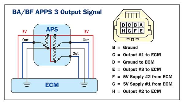
So, a 6 pin accelerator pedal position sensor wiring diagram is, two wires are for the earth, two for the input voltage, and two for signals back to the ...

Throttle Body Connector Wiring Vw Gti Mkvi Forum Vw Golf R Forum Vw Golf Mkvi Forum Vw Gti Forum Golfmk6 Com
The throttle position sensor reads the position of the gas pedal in your Engine Control Unit. Here are some signs indicating your throttle position sensor needs to be replaced: if your engine stalls or misfires, if the engine is in poor performance; if there is a loss of power; if the transmission does not shift correctly.

Throttle Position Sensor Wiring Diagram 08 Int Prostar Isx Cummins Me And A Mechanic New Sensor And Checking With
How to Test Crankshaft and Camshaft sensors 1 Accelerator Pedal Position Sensor How we rebuilt our Chevy Small-Block V-8 engine | Redline Rebuilds Explained - S1E2 How To: Remove\\Install A LS Oil Pump Install. (While Engine IS Still In Car.) ... V6 wiring diagram and connectors H002 11 VN Model (from Oct 1989) & VP Model V6 wiring diagram and ...
Accelerator Pedal Position Sensors Apps
(Originally posted in r/mazda3) **GENERIC WARNING:** This guide is how I installed a WOT Box on my MZR 2.5. Your mileage may vary by model year, engine production series, production location, etc. As such, I am not responsible for any damages as a result of this guide. You assume all responsibility for all modifications and any resulting damages from improper installation, regular use, or just plain idiocy. This mod will dump fuel into the exhaust, so there is an increased risk for fire/destro...

Rx8 Dbw Throttle Pinout G4 Link Engine Management Forums
code p 0122 refers to throttle position (TP) sensor A/ accelerator pedal position (APP) sensor A low input === causes wiring short to ground--TP/APP sensor --ECM There are 3 responses to p 0122 and all refer to TP switch /sensor plus wiring open /short to ground/ short to positive

Throttle Position Sensor Toyota Engine Control Systems
Throttle control unit, engine management system (petrol) 10: F8: Accelerator Pedal Position Sensor, A / C Compressor Clutch Relay, Fuse / Relay Box Cooling Fan: 10: F9: Sound signal: 15: F10: Rear window washer pump motor: 10: F11: Engine Management, Glow Plugs Heating / Air Conditioning System Crankcase Ventilation Heater (Diesel) 20: F12 ...
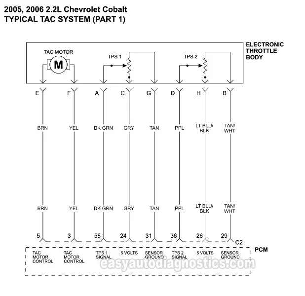
Part 1 Tac System Wiring Diagram 2005 2009 2 2l Chevrolet Cobalt
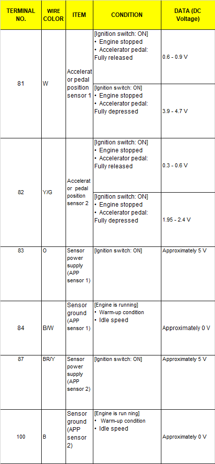
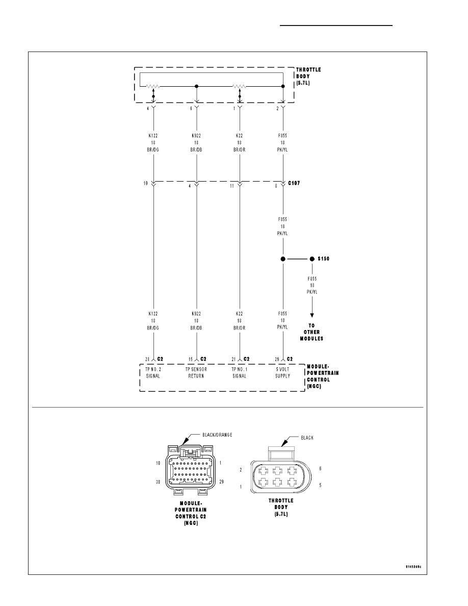
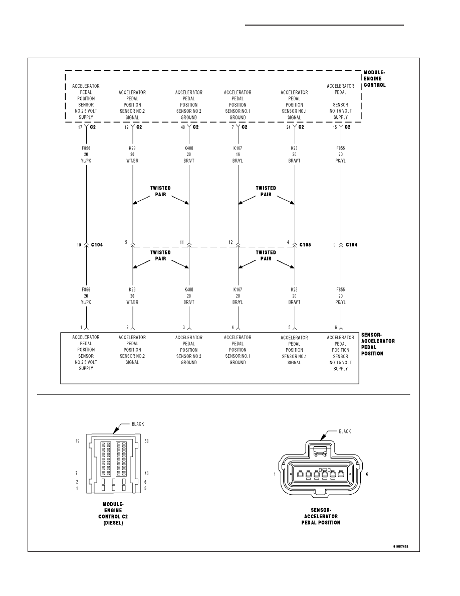
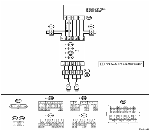
This is the repair procedure for the accelerator pedal position sensor. CIRCUIT DESCRIPTION ... WIRING DIAGRAM. INSPECTION PROCEDURE.5 pages
Dbw Pedal Wiring Questions Ls1tech Camaro And Firebird Forum Discussion
These wires must be connected to your vehicle chassis, and are the vital steps to knowing How to Wire your VQ35 Swap. Secondary Engine Operation Pinouts : Chassis Ground - Pin 1 - Black. Chassis Ground - Pin 115. Chassis Ground - Pin 116. Sensor Ground - Accelerator Pedal Position Sensor 1 - Pin 82. Sensor Ground - Accelerator.
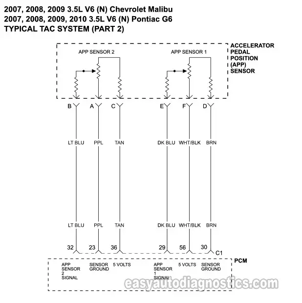
Throttle Body Tac Circuit Wiring Diagram 2007 2008 3 5l Malibu
A problem with the throttle actuator control system may cause the PCM to restrict its operations. This is known as the "limp home mode" or a "fail-safe" position, where the engine is held at idle or has limited power to prevent unwanted acceleration. Note: The definition of code P2111 may be different depending on the vehicle manufacturer.
Accelerator Pedal Position Sensors Apps
P02E2 Reduced signal from the intake flap actuator. A possible cause may be a shorted wire . P02E8 Low pulse signal coming from the damper position sensor. The problem must be sought in the integrity of the wiring and contact elements . P029C Problems associated with the operation of the first nozzle.

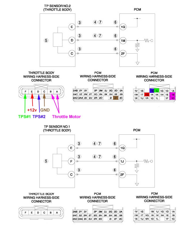
Please Help With Wiring My Tps Position Of Each Wire Kia Forum
WHAT IS APP? · SENSOR LOCATION: · HOW TO TEST : · WIRING DIAGRAM : · WIRING TECHNICAL DATA: · TECHNICAL SPECIFICATION: · Accelerator Pedal Released Position Learning.
Gsic Global Service Information Center
... control system inputs and outputs Basic Electrical Wiring, Electrical Circuit Diagram, Mécanicien ... Sensor TPS y sus fallas | Lapps.es Portal Mécanica.

Tps Apps Throttle Position Sensor 5 9l Cummins Prosource Diesel
1992 Cadillac Seville - Where is the obd connector on the 1992 seville- question about Cars & Trucks

Gsic Global Service Information Center
Answered Can Anyone Tell Show Me The Wiring Diagram For The 4 Pin Tps Kia Amanti Cargurus

Dodge Ram Truck 1500 2500 3500 Manual Part 990
1 8t Throttle Pedal Wiring Club Gti
Circuit Diagram

Wiring Diagram Of A Forklift Accelerator Pedal Circuit Download Scientific Diagram

Pic Request Throttle Position Sensor Connector Wiring Lexus Is Forum

Understanding The Efi Process Page 6 Of 7 Motoiq
1

Throttle Position Sensor Toyota Engine Control Systems
Gsic Global Service Information Center
Ls1 To Ls2 Throttle Position Sensor Wiring Swap Questions Corvetteforum Chevrolet Corvette Forum Discussion
Drive By Wire Throttle Wiring Question Rx8club Com
Subaru Crosstrek Service Manual Dtc P2123 Throttle Pedal Position Sensor Switch D Circuit High Diagnostic Procedure With Diagnostic Trouble Code Dtc
Gsic Global Service Information Center

For The Wiring Diagram Throttle Position Sensor Plug It Use 4 Wires And Accidentally I Mix Them Up And To Connect Them
1996 1998 Tp Sensor Circuit Diagram 2 0l Neon


Comments
Post a Comment