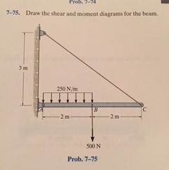
42 7.75 draw the shear diagram for the beam.
This video explains how to draw shear force diagram and bending moment diagram with easy steps for a cantilever beam loaded with a concentrated load. Shear f... Experts are tested by Chegg as specialists in their subject area. We review their content and use your feedback to keep the quality high. Transcribed image text: 7-61. Draw the shear and moment diagrams for the beam. "7-64. Dr 20 kip 20 kip 4 kip/ft 30 ft 15 ft 15 ft Prob. 7-61.
Beam Calculator Online (Calculate the reactions, Draws Bending Moment, Shear Force, Axial Force) We updated the beam calculator interface and added additional features for calculating beams (calculation of statically indeterminate beams, image saving and section selection)! GO TO NEW INTERFACE (BEAM)>. GO TO NEW INTERFACE (FRAME/TRUSS)>.

7.75 draw the shear diagram for the beam.
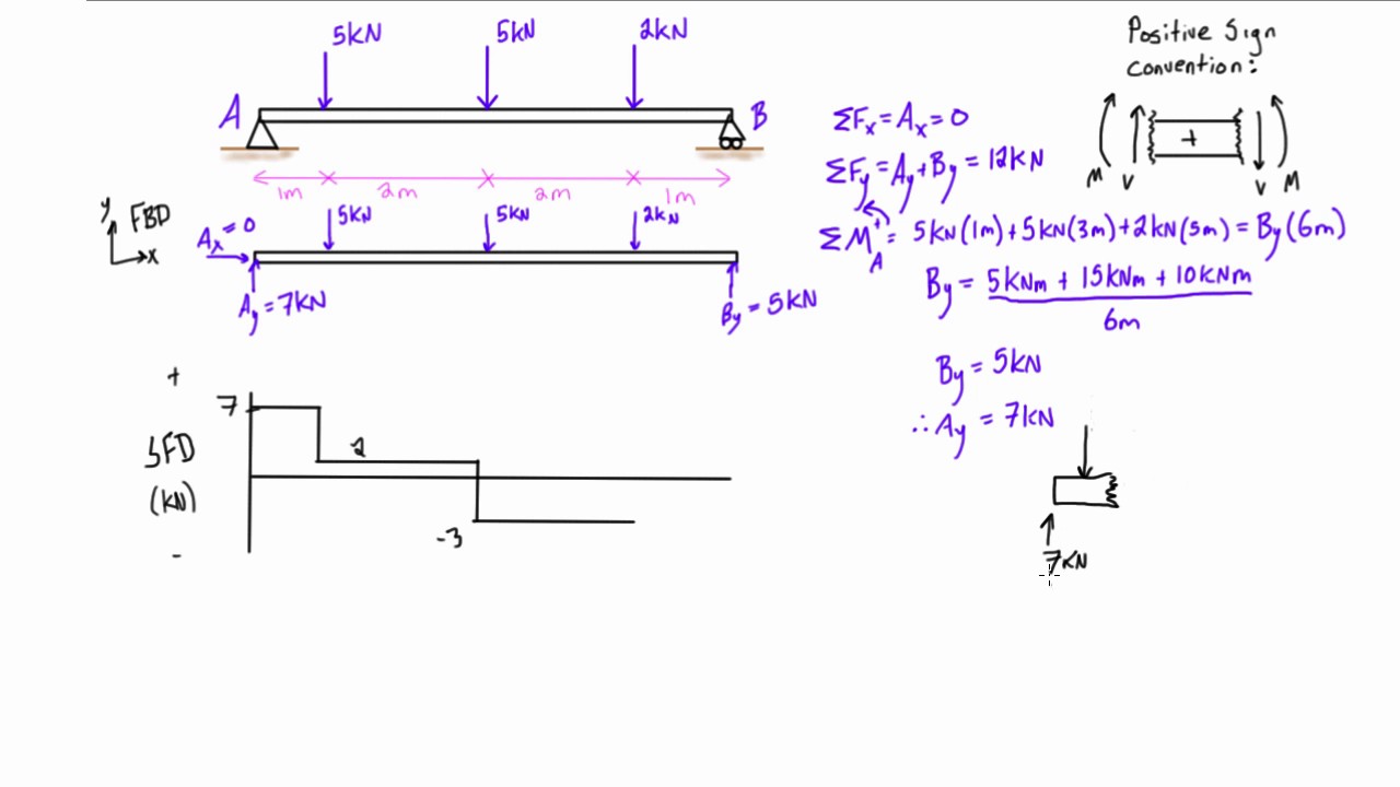
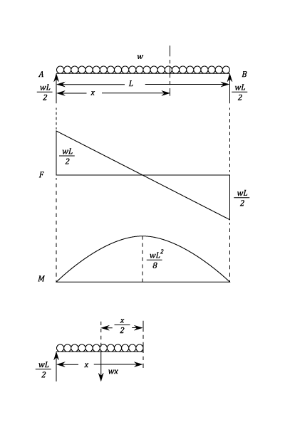
Shear and Moment Functions. Since there is a discontinuity of distributed load and also a concentrated load at the beam’s center, two regions of x must be considered in order to describe the shear and moment functions for the entire beam. M = ( − 2. 5 x 2 2 + 1 5. 7 5 x 2 + 9 2. 5) k N ⋅ m. Free online beam calculator for generating the reactions, calculating the deflection of a steel or wood beam, drawing the shear and moment diagrams for the beam. This is the free version of our full SkyCiv Beam Software. This can be accessed under any of our Paid Accounts, which also includes a full structural analysis software. a) Calculate the shear force and bending moment for the beam subjected to a concentrated load as shown in the figure. Then, draw the shear force diagram (SFD) and bending moment diagram (BMD). b) If P = 20 kN and L = 6 m, draw the SFD and BMD for the beam. P kN L/2 L/2 A B EXAMPLE 4
7.75 draw the shear diagram for the beam.. Draw the shear and moment diagrams for the beam. 2 kip 2 kip 2 kip 2 kip Kip) M(Kp-ft) 6—1. Draw the shear and moment diagrams for the shaft.The hearings at A and B exert only vertical reactions on the shaft. V(XN) 800 mm 250 mm 75 24 kN Draw the shear and moment diagrams for the beam shown in Fig. 6–7a. (a) L w 0 w —— 2 0 L (b) 2– L 3 w —— 2 0 L — 3 w 0 L2 w 0 Solution Support Reactions.The distributed load is replaced by its resultant force and the reactions have been determined as shown in Fig. 6–7b. Shear and Moment Functions.A free-body diagram of a beam ... Nov 23, 2018 · Draw The Shear And Moment Diagrams For Beam 7 75. November 23, 2018 - by Arfan - Leave a Comment. Mathcad 07 001 mcd ering mechanics statics pages 351 ering mechanics statics pages 351 1 draw the shear and moment diagrams draw the shear force and bending moment. Solved 7 75 Draw The Shear And Moment Diagrams For B Chegg. 4.3 Shear- Moment Equations and Shear-Moment Diagrams The determination of the internal force system acting at a given section of a beam : draw a free-body diagram that expose these forces and then compute the forces using equilibrium equations. The goal of the beam analysis -determine the shear force V and
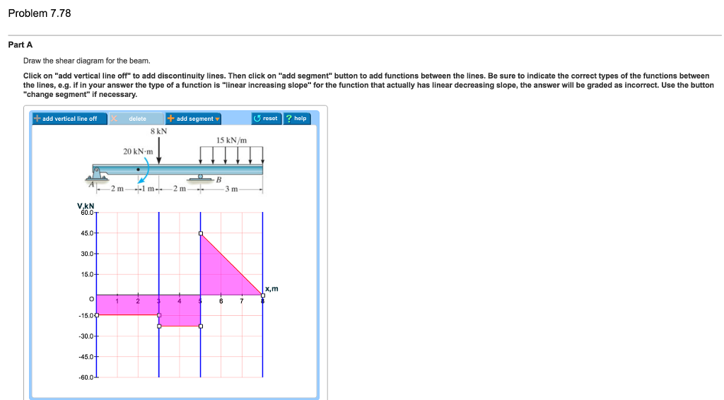
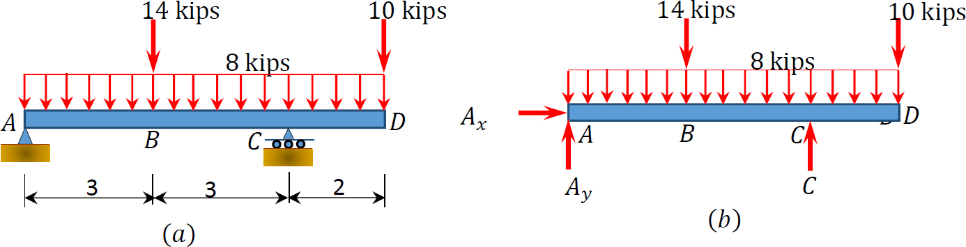
Problem 7.75 Part A Draw the shear diagram for the beam. Click on "add discontinuity" to add discontinuity lines. Then click on "add segment" button to add functions between the lines. Part B Draw the moment diagram for the beam. Click on "add discontinuity" to add discontinuity lines. Then click on "add segment" button Transcribed image text: Problem 7.55 Part A Draw the shear diagram for the beam. Click on "add vertical line off to add discontinuity lines. Then click on "add segment" button to add functions between the lines. Nov 29, 2021 · 5.0 Drawing Shear Force and Bending Moment Diagrams – An Example. 5.1 Video Tutorial; 5.2 Calculating the support reactions; 5.3 Drawing the shear force diagram; 5.4 Drawing the bending moment diagram; 6.0 Relating Loading, Shear Force and Bending Moment. 6.1 Case 1: Uniformly distributed loading; 6.2 Case 2: Point force loading; 6.3 Case 3 ... 1. Q. Analyze two span continuous beam ABC by slope deflection method. Then draw Bending moment & Shear force diagram. Take EI constant. Fixed end moments are Since A is fixed Slope deflection equations are In all the above 4 equations there are only 2 unknowns and accordingly the boundary conditions are
a) Calculate the shear force and bending moment for the beam subjected to a concentrated load as shown in the figure. Then, draw the shear force diagram (SFD) and bending moment diagram (BMD). b) If P = 20 kN and L = 6 m, draw the SFD and BMD for the beam. P kN L/2 L/2 A B EXAMPLE 4 Free online beam calculator for generating the reactions, calculating the deflection of a steel or wood beam, drawing the shear and moment diagrams for the beam. This is the free version of our full SkyCiv Beam Software. This can be accessed under any of our Paid Accounts, which also includes a full structural analysis software. Shear and Moment Functions. Since there is a discontinuity of distributed load and also a concentrated load at the beam’s center, two regions of x must be considered in order to describe the shear and moment functions for the entire beam. M = ( − 2. 5 x 2 2 + 1 5. 7 5 x 2 + 9 2. 5) k N ⋅ m.
The Blocks Shown In The Figure Are At Rest Block A Has A Mass Of 7 75 Kg And Block B Has A Mass Of 2 10 Kg The Coefficient Of Static Friction Between
Solved 7 75 Draw The Shear And Moment Diagrams For The Beam Chegg Com

Sustainability Free Full Text Stability Analysis Of Paste Filling Roof By Cut And Fill Mining Html

Shear Force And Bending Moment Of Beams Beams Propped Cantilever Beam When A Support Is Provided Pdf Document

Practice Exams Mcgraw Hill Education Access Engineering
Centroids Moments Of Inertia

Maximum Shear Force An Overview Sciencedirect Topics
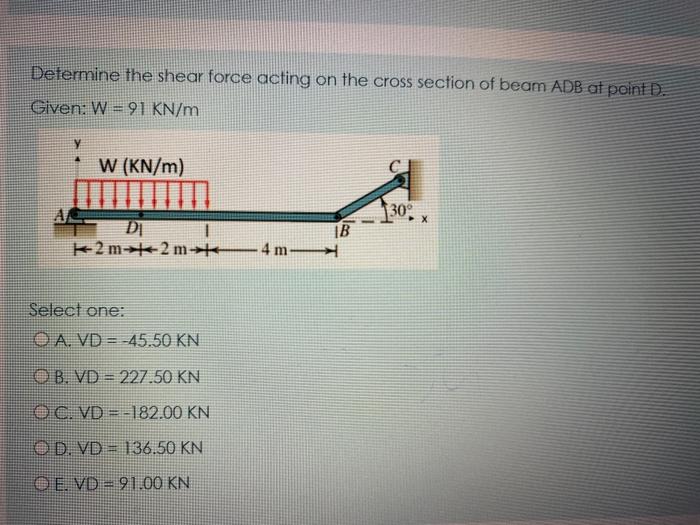
Answered Determine The Shear Force Acting On The Bartleby
Solved Are These The Correct Shear And Moment Diagrams For Chegg Com
2

Von Mises Stress Distribution For 180 O Bent Tube R B 7 75 Mm Download Scientific Diagram

Mechanical Properties Springerlink

Drawing Shear And Moment Diagrams For Beam Youtube
1 4 Internal Forces In Beams And Frames Engineering Libretexts
Shear Force And Bending Moment Diagrams Example 2 Multiple Point Loads Youtube

69 87 Pdf Document
2
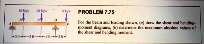
Solved 16 Kip Gum Problem 7 75 For The Beam And Loading Shown Draw The Shear And Bending Moment Diagrams B Determine The Maximum Absolute Values Of The Shear And Bending Moment Fi 60 J
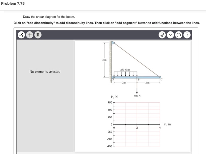
Solved Problem 7 75 Draw The Shear Diagram For The Beam Chegg Com
2

2 10 Points Consider The Beam Shown Below A Draw The Complete Shear Diagram With Corresponding Homeworklib
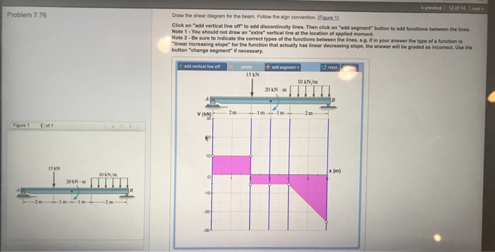
Solved Previous 12 Of 14 Problem 7 76 Draw The Shear Diagram Chegg Com

2014 Icc 600 Icc Digital Codes

Determine The Normal Shear Force And Bending Moment At C And D Youtube
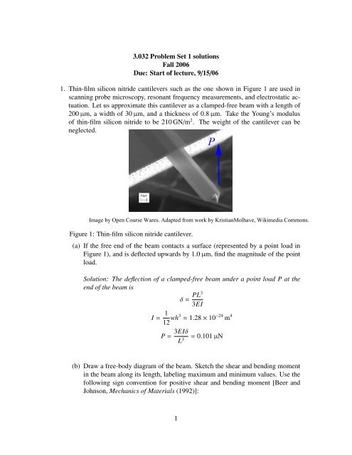
3 032 Problem Set 1 Solutions Fall 2006 Due Mit Opencourseware
2
1
Shear Force And Bending Moment Materials Engineering Reference With Worked Examples

Shear Force And Bending Moment Of Beams Beams Propped Cantilever Beam When A Support Is Provided Pdf Document

Applied Strength Of Materials For Engineering Technology
2
Solved Question 1 5 P M Q 2 Me 4cm In The Given Gure All The Dimensions Loading Condition And Cross Section Of The Beam Are Given If The Course Hero

2 10 Points Consider The Beam Shown Below A Draw The Complete Shear Diagram With Corresponding Homeworklib

Mcgraw Hill Education All Rights Reserved No Reproduction Or Distribution Without The Prior Written Consent Of Mcgraw Hill Education Pdf Geometry Space

Full Article A Superconvergent Elastically Coupled Double Beam Element For Analysis Of Adhesively Bonded Lap Joints

Seismic Behaviour Of Rws Moment Connections To Deep Columns With European Sections Sciencedirect
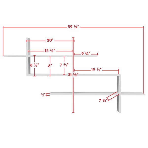
Wade Logan Lacombe 3 Piece Accent Shelf Reviews Wayfair

Ch7 31 50 Pdf Bending Copyright
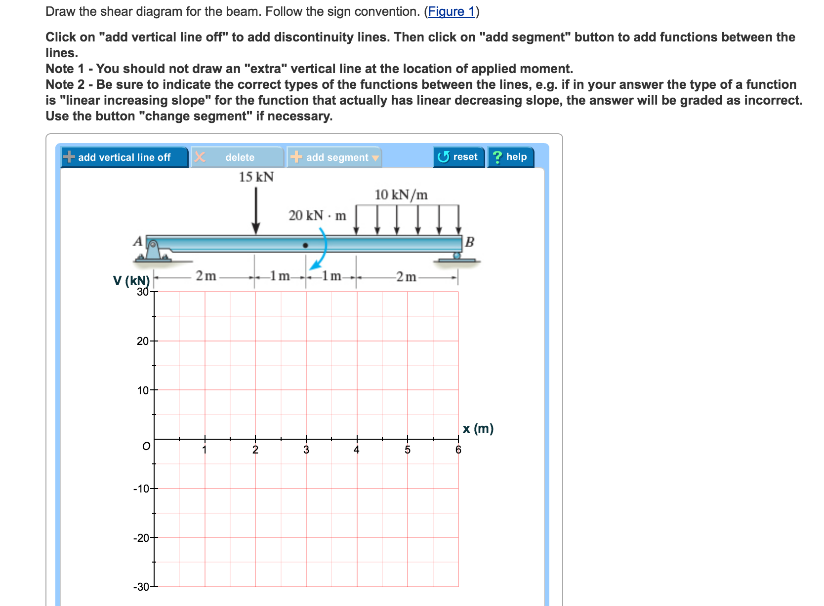
Solved Draw The Shear Diagram For The Beam Follow The Sign Chegg Com
2

The 100 Most Cited Articles In Orthodontic Journals In The Last 20 Years American Journal Of Orthodontics And Dentofacial Orthopedics
Deflection Of Symmetric Beams


Comments
Post a Comment