41 gps receiver circuit diagram
Hi Reddit! I've been dreaming of having a multicopter for almost 2 years. Just before Christmass I've got (hopefully) all [required parts](http://imgur.com/G0MpotV) and now I have 11 days to put it all together. I will be checking in daily to update you on my success(or failure). Your help is more than welcome! Here we go! **[Hardware:](http://imgur.com/CiREYbi)** * Flight Controller - HKPilot Mega 2.7 * Power Module - 10s Power sensor and BEC Module ( XT-60 connectors) * OSD - Minim OSD v1.... "to go around," early 15c., from circuit (n.). Related: Circuited; circuiting.
TL;DR; Someone tried to break into my van in the nicest neighborhood of Seattle last night. What makes for a safe parking spot and what can we do to make our vans more secure? I plan to install padlocks/bolts and window screens on the back and side doors, a folding metal security gate between the front and rear, a hidden magnetized kill switch somewhere on the dashboard, and a cheap diy GPS system that works in any country in the world. Links and details are provided in the discussion at the bot...

Gps receiver circuit diagram
**tl;dr:** links to 3D models, and details on head unit, install parts, in links below.   **3D model:** https://i.imgur.com/sIRwzYr.png   I was busy replacing the crapola stock head unit on my '16 GT86 with a cheap Android double DIN head unit, when I came to realize that neither the supplied mounting brackets, nor the stock mounting brackets, not the after market DDIN side facia spacers I bought are going to work to make this head unit fit the 86.   The head un... GPS (talker) "A" "B" Shield "A" "B" Shield (listener) RADAR (listener) Chart Plotter (talker) To other devices. Figure 1: NMEA 0183 Interface Circuit . Multiple interface circuits may be provided to accommodate vessels with more than one talker, but each circuit has only one talker and is independent and wired separately. The IR sensor-controlled robotic vehicle project circuit is shown in the figure. The block diagram of IR-controlled robotic vehicles consists of different blocks such as motors and motor diver interfaced with the 8051 microcontrollers, battery for power supply, IR receiver block, and TV remote or IR remote as shown in the figure.
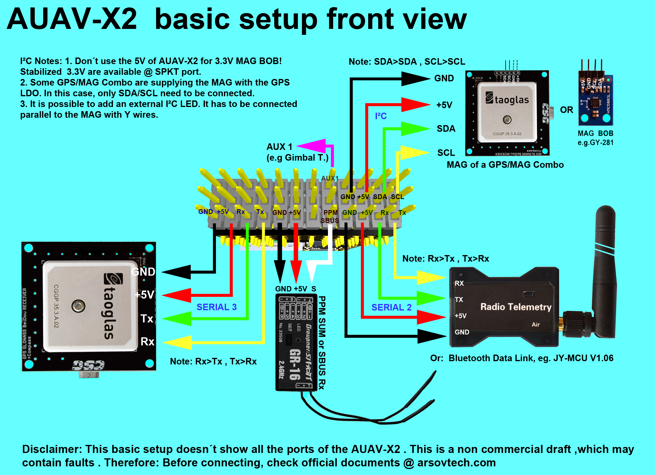
Gps receiver circuit diagram. Aug 23, 2020 · J. GPS Module. The GPS module often combines GPS receiver and magnetometer to provide latitude, longitude, elevation, and compass heading from a single device. GPS is an important requirement for waypoint navigation and many other autonomous flight modes. Without GPS, drones would have very limited uses. Hello everyone. I'm attempting to put together a video that covers multirotor frequently asked questions. The goal is to touch a wide variety of topics and provide many useful resources to help people find the answers to get started. My plan is low tech: do a screen capture of browsing through various websites and videos to show what the hobby has to offer. All links will be clearly visible and linked in the video description so there isn't any concern of me using someone else's content. Video ... CFI SE and CFI-I writeup This week I passed my CFI initial exam for single engine airplanes and two days later I took my CFI-I exam with a different examiner and passed. This was a huge step for me! I’m working on getting my MEI next, and then I am excited to start a career in aviation. Preparing for these exams was a lot of work and I spent a lot of hours studying and stressing. I wanted to make a write up to help anyone else that may be going down this route. \*Full disclosure: the quick t... "product of distillation, a fluid found in the receiver of a distilling apparatus," 1845; see distill + -ate (1).
Nov 20, 2021 · Pinout of M.2 (NGFF) connectorM.2 (Next Generation Form Factor, NGFF), is a specification for computer expansion cards. Having a small and flexible physical specification, the M.2 is suitable for solid-state storage applications, especially when used in small devices such as ultrabooks or tablets. 1934, from a merger of transmitter + receiver. • Circuit made of a set of pre-defined logic, known as standard cells • E.g., basic logic gates, 1-bit adder, D FF etc • Layout of a cell is pre-determined, but layout of the complete circuit is customized • Masks needed for all layers Smart Machine Smart Decision SIM868_Hardware_Design_V1.00 11 2016-05-15 Feature Implementation Power supply 3.4V ~4.4V Power saving Typical power consumption in sleep mode is 0.65 mA (AT+CFUN=0 )
Dec 13, 2018 · The low-battery indication circuit consists of transistor T9, preset VR2, zener diode ZD2, resistors R5, R6 and R7, LED2 and capacitor C2. The 12V supply voltage from BATT.1 is applied to the low-battery indicator circuit with full load (not more than 1000 watts) connected to the inverter output. The voltage across the load is 230V AC. 1610s, "an illustrative figure giving only the outlines or general scheme of the object;" 1640s in geometry, "a drawing for the purpose of demonstrating the properties of a figure;" from French diagramme, from Latin diagramma "a scale, a musical scale," from Greek diagramma "geometric figure, that which is marked out by lines," from diagraphein "mark out by lines, delineate," from dia "across, through" (see dia-) + graphein "write, mark, draw" (see -graphy). Related: Diagrammatic; diagrammatically. The verb, "to draw or put in the form of a diagram," is by 1822, from the noun. Related: Diagrammed; diagramming. mid-14c., receivour (mid-13c. as a surname, probably in the "government clerk" sense), "a recipient; a receiver (of stolen goods); person who knowingly harbors criminals," also "government official appointed to collect or receive money due," agent noun from receive, or from Old French recevere (Modern French receveur), agent noun from recievere. From late 14c. as "receptacle, container." As a telephone apparatus, from 1877; in reference to a radio unit, from 1891; in U.S. football sense, from 1897. Middle English also has receitour in the sense "receiver of stolen goods" (late 14c.); also compare receptor. Oct 23, 2020 · The functional diagram in Fig. 1 illustrates the operation of a directional coupler, followed by a description of the related performance parameters. The top diagram is a 4-port coupler, which includes both coupled (forward) and isolated (reverse, or reflected) ports. The lower diagram is a 3-port structure, which eliminates the isolated port.

GPS receiver module | GPS module app note,manufacturers
tracked moreover minimal polyphonic lottery tops framed aside outsourcing licence adjustable allocation michelle essay discipline amy ts demonstrated dialogue identifying alphabetical camps declared dispatched aaron handheld trace disposal shut florists packs ge installing switches romania voluntary ncaa thou consult phd greatly blogging mask cycling midnight ng commonly pe photographer inform turkish coal cry messaging pentium quantum murray intent tt zoo largely pleasant announce constructed a...
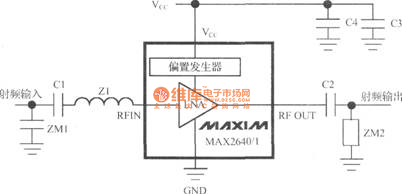
MAX2641-based GPS receiver LNA circuit - Basic_Circuit ...
3 MHz - 5 MHz Cascade Regenerative Receiver - WD5HOH. 3 x Superregenerative Receivers - RSGB. 40m MRX-40 Receiver - K8IDN. Multiband HF Direct Conversion Receiver - RSGB. 7 MHz Rock-Bending Receiver - WI5W. HF MicroR2 SSB/CW Receiver. HF DCR Polyphase Receiver - G0UPL. AM Receiver with PLL - 4046. Medium Wave Receiver for DX

Block diagram of dual-band GPS receiver ( f 0 : standard ...
Aug 31, 2017 · The TSOP1733 receiver will receive the only 33KHz signal. Why use TSOP Based IR Receiver. The simple IR sensor gives false detection when using in presence of the sunlight. The signal sends from the normal IR led can not cover a long distance.

Block diagram of the GPS receiver. | Download Scientific ...
late 14c., "a circumference; a periphery, a line going around (an area), whether circular or not; a circular or circuitous course," from Old French circuit (14c.) "a circuit; a journey (around something)," from Latin circuitus "a going around," from stem of circuire, circumire "go around," from circum "round" (see circum-) + ire "to go" (from PIE root *ei- "to go"). From c. 1400 as "space enclosed within certain limits." Hence, "district in which any business involving periodic journeys is done (1570s), especially of judicial assignments involving the journey of a judge from one place to another; in reference to routes followed by itinerant entertainers from 1834. Hence also circuit-rider "Methodist minister who rides a circuit, preaching successively in different stations" (by 1834); to ride circuit "take a roundabout course" is from 1650s. Electrical sense "arrangement by which a current is kept up between two poles" is from 1746. Circuit-breaker "device for automatically opening an electrical circuit" is r

Block diagram of the GPS receiver. | Download Scientific ...
Hello, I'm new to Arduino and recently got an [Elegoo Uno R3](https://www.amazon.com/gp/product/B01EWOE0UU/ref=oh_aui_detailpage_o02_s00?ie=UTF8&psc=1) and a [WS2812B addressable LED strip](https://www.amazon.com/gp/product/B018WZENK2/ref=oh_aui_detailpage_o02_s00?ie=UTF8&psc=1). I can't seem to make anything happen with the LEDs. I've tried various pieces of code from both the FastLED and Adafruit_NeoPixel libraries. I have managed to get console writing working so I know that my code i...
gps circuit Page 2 : RF Circuits :: Next.gr
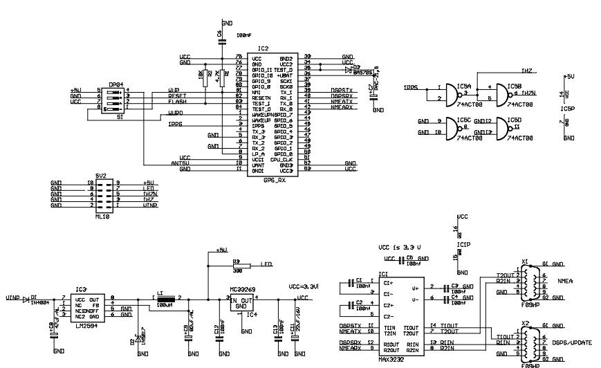
Nov 29, 2021 · The prototype is shown in Fig. 4. The circuit diagram of ESP32 based GPS receiver is shown in Fig. 5. It is recommended to use an external 3.7V battery power source for the circuit. Fig. 4: Author’s prototype Fig. 5: Circuit diagram of ESP32 based GPS receiver. The TFT ILI9163 display works on five pins other than the VCC, LED, and GND pins.

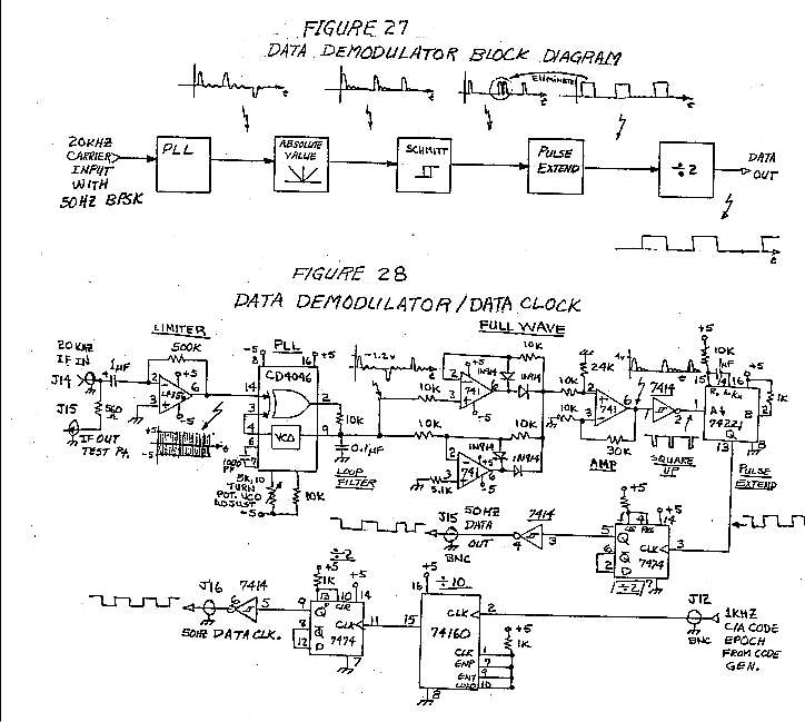
APRS Position and Data Telemetry
Oct 06, 2016 · Automatic plant watering system circuit and working The circuit diagram of the automatic plant watering system is shown in Fig. 2. The circuit comprises an Arduino UNO board, a soil moisture sensor, a servo motor, a 12V water pump and an L293D (IC1) motor driver IC to run the water pump.
GPS-GSM Based Vehicle Tracking System Using Microcontroller
Welcome to the Scheme-it | Free Online Schematic and Diagramming Tool | DigiKey Electronics Scheme-it project. Scheme-it is a free online schematic drawing tool that will allow you to produce professional looking schematic diagrams, add corresponding part numbers, and share your schematic with others.
Technoblogy - I2C GPS Module PCB
Multipath interference is a phenomenon in the physics of waves whereby a wave from a source travels to a detector via two or more paths and the two (or more) components of the wave interfere constructively or destructively. Multipath interference is a common cause of "ghosting" in analog television broadcasts and of fading of radio waves.
gps circuit Page 2 : RF Circuits :: Next.gr
late 15c., "office of a receiver of public revenues," from receiver + -ship. As "condition of being under control of a receiver," 1884.

GPS USB Reference Design with the MAX2769 - Reference ...
​ ​ "control" as for the amplifier that controls the signal strength, there are two main functions: 1. Control the signal strength to a certain extent: under normal circumstances, the signal strength received by the antenna cannot meet the needs of information processing, so the amplifier is required to increase the signal strength to a certain extent, the absolute signal strength The unit is DBM, 0 DBM is 1MW, 10 DBM is 10MW, which is logarithmic growth rela...
It's been a good few weeks for the homelab
Aug 20, 2019 · Automatic water-level controller circuit Leaf switches S1 and S2 (used in tape recorders) are fixed at the top of the sensor units such that when the floats are lifted, the attached 5mm dia. (approx.) aluminium rods push the moving contacts (P1 and P2) of leaf switches S1 and S2 from normally closed (N/C) position to normally open (N/O) position.

Beyond Locative Media
also micro-circuit, in electronics, "integrated circuit," 1959, from micro- + circuit (n.). Related: Microcircuitry.
GPS Clock using Arduino Circuit Diagram
1918 (Venn's diagram is from 1904), named for English logician John Venn (1834-1923) of Cambridge, who explained them in the book "Symbolic Logic" (1881).
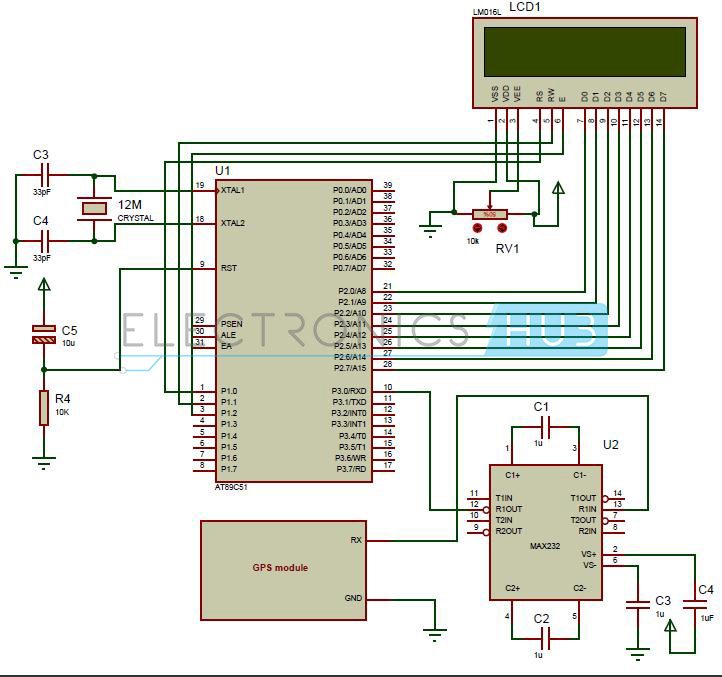
Interfacing GPS with 8051 Microcontroller (AT89C51)
In radio communications, a radio receiver, also known as a receiver, a wireless, or simply a radio, is an electronic device that receives radio waves and converts the information carried by them to a usable form. It is used with an antenna.The antenna intercepts radio waves (electromagnetic waves) and converts them to tiny alternating currents which are applied to the …

Block diagram of the GPS receiver. | Download Scientific ...
I am excited to have successfully built my first transceiver and made my first QRP contact! There is a long and proud tradition of building your own radio in the amateur radio community. It is was a great learning experience and a lot of fun! It has rekindled my interest in electrical engineering and tinkering. (See my QRZ page for embedded pictures, links, and smoke test video-AD0WE.) At $50, the QCX transceiver is one of the cheapest full-featured QRP CW kits on the market. Kits are available...
Prototype a Robotic Lawn Mower
A list of Origami designs with special magical effects—**FINISHED**! **My heartfelt thanks to everyone** **who contributed!!!** I introduced it to my campaign as a reward for an adventure in a Demiplane of Paper, the premise being a powerful witch either created or collected these designs in books that have a limited set of enchanted papers keyed to their respective designs, giving the GM some latitude about how many figures their players could create. More complex designs would require practi...
gps circuit : RF Circuits :: Next.gr
May 30, 2016 · Unit 1.2.3 GNSSC: Basic GNSS and en route GPS navigation principles – all categories. Unit 1.2.4 PAKA: PPL aeronautical knowledge – aeroplane. Unit 1.2.5 PAKH: PPL aeronautical knowledge – helicopter

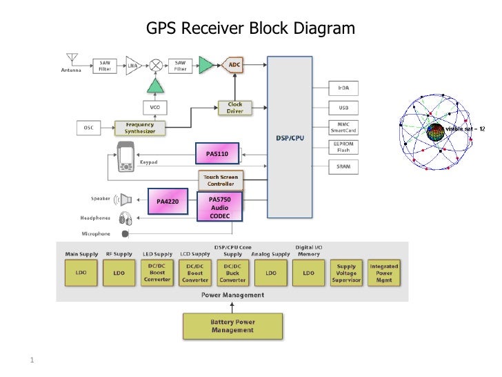
8. Block diagram of a generic GPS receiver. | Download ...
also short-circuit, 1854, in electricity, from short (adj.) + circuit (n.). As a verb, introduce a shunt of low resistance," from 1867; intransitive sense from 1902; in the figurative sense is recorded by 1899. Related: short-circuited; short-circuiting.
Basics of the Global Positioning System
The IR sensor-controlled robotic vehicle project circuit is shown in the figure. The block diagram of IR-controlled robotic vehicles consists of different blocks such as motors and motor diver interfaced with the 8051 microcontrollers, battery for power supply, IR receiver block, and TV remote or IR remote as shown in the figure.

Pin on 8051 Tutorial & Projects
GPS (talker) "A" "B" Shield "A" "B" Shield (listener) RADAR (listener) Chart Plotter (talker) To other devices. Figure 1: NMEA 0183 Interface Circuit . Multiple interface circuits may be provided to accommodate vessels with more than one talker, but each circuit has only one talker and is independent and wired separately.
**tl;dr:** links to 3D models, and details on head unit, install parts, in links below.   **3D model:** https://i.imgur.com/sIRwzYr.png   I was busy replacing the crapola stock head unit on my '16 GT86 with a cheap Android double DIN head unit, when I came to realize that neither the supplied mounting brackets, nor the stock mounting brackets, not the after market DDIN side facia spacers I bought are going to work to make this head unit fit the 86.   The head un...
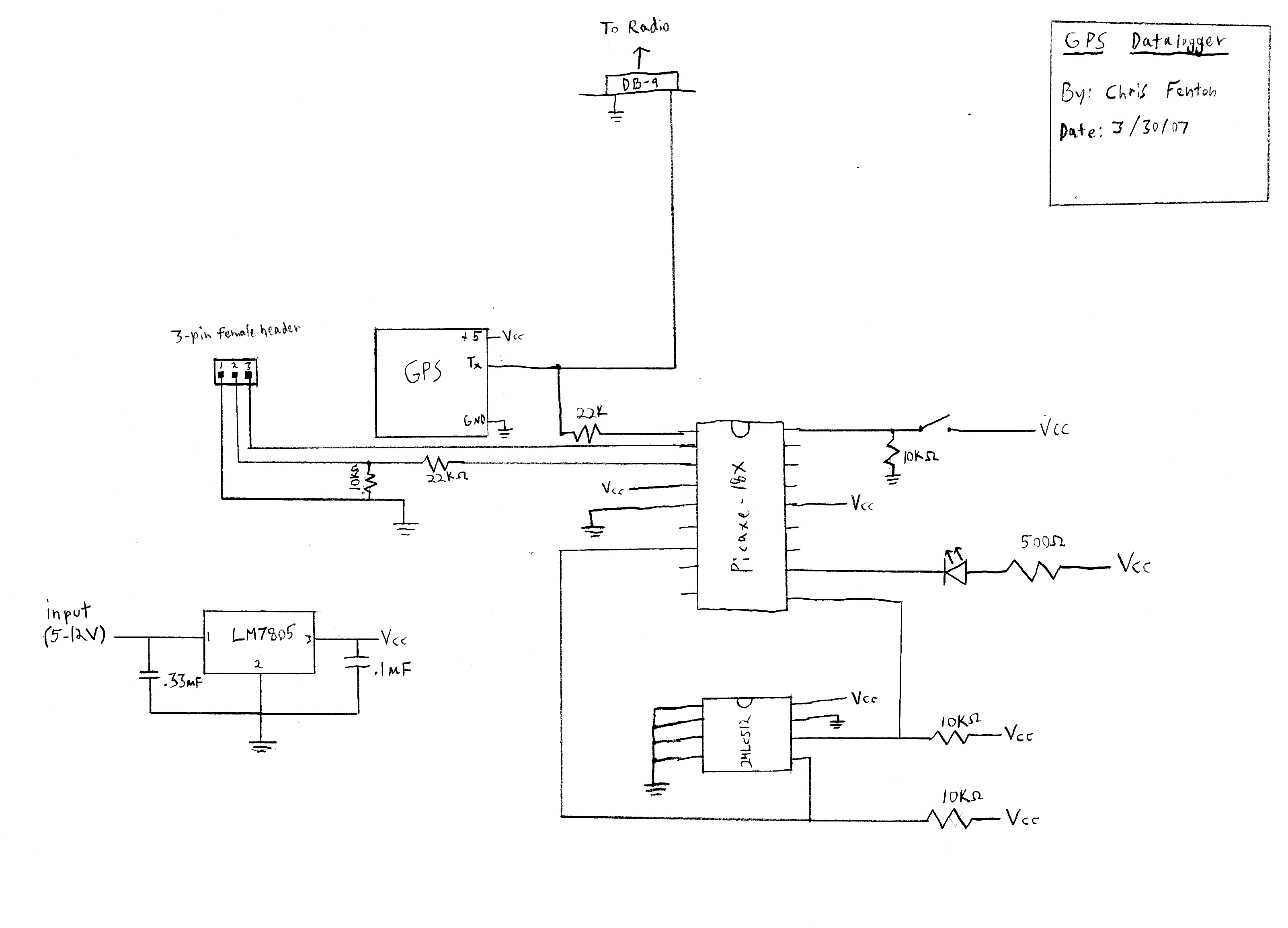
Homemade GPS Receiver
Low-Power IC Packs GPS Receivers 2 - Signal_Processing ...

2: Systematic Block Diagram of a GPS Receiver | Download ...

GPS receiver block diagram with the test circuits and test ...
mICRO Minds: Vehicle tracking system using GPS and GSM modem
gps circuit Page 3 : RF Circuits :: Next.gr
MRFICl505R2 - based GPS receiver RF front-end circuit ...

Homemade GPS Receiver
Pixhawk Mini Osd Module Wiring Diagram
How to build your own GPS receiver - ExtremeTech

Magellan Gps Usb Wiring Diagram | USB Wiring Diagram
U-Blox GPS receiver Board - Signal_Processing - Circuit ...
Gps -analog block diagram
LEAP - Satellite Missions - eoPortal Directory

Coordinates : A resource on positioning, navigation and ...
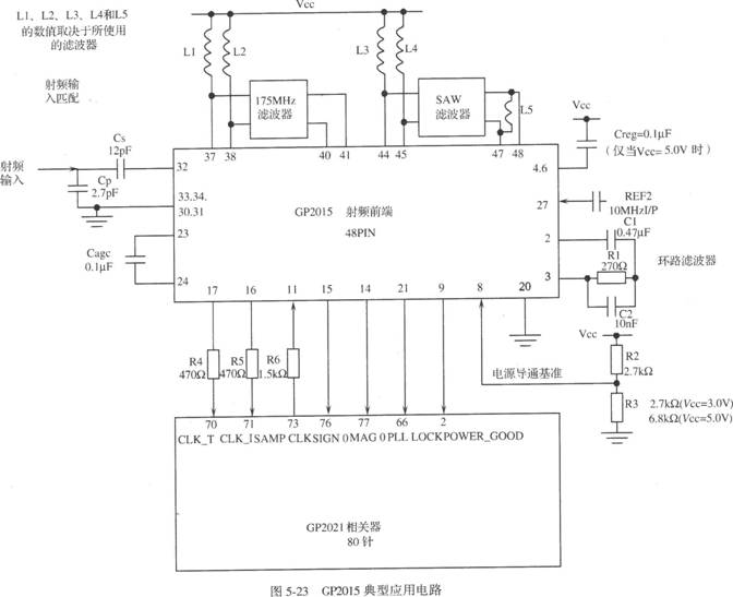
GP2015 - based GPS receiver RF front-end circuit - Basic ...

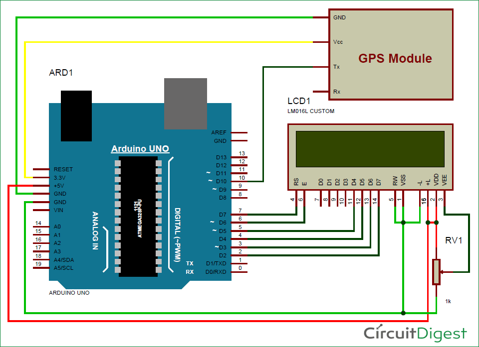
How to Make Arduino as Standalone GPS Receiver with 16x2 ...

Arduino GPS Clock


Comments
Post a Comment