41 communication loop diagram
Basics 19 Instrument Loop Diagram : Basics - 1 Plant 1-Line . Basics - 2 7.2 kV One-Line . Basics - 3 4.16 kV One-Line . Basics - 4 600 V One-Line . Basics - 5 MCC One-Line . Basics - 6 Three-Line . Basics - 7 Three-Line . Basics - 8 MOV Block Diagram Basics - 8 MOV Elementary Diagram . Basics - 9 Pump Schematic . Communication diagrams describe the interactions of two or more things in the system that perform a behavior that is more than any one of the things can do alone. could be converted to/from or replaced by) to a simple sequence diagram … To the experienced instrument technician who has had to work on systems lacking such documented detail, this information is highly valued. By clicking ...
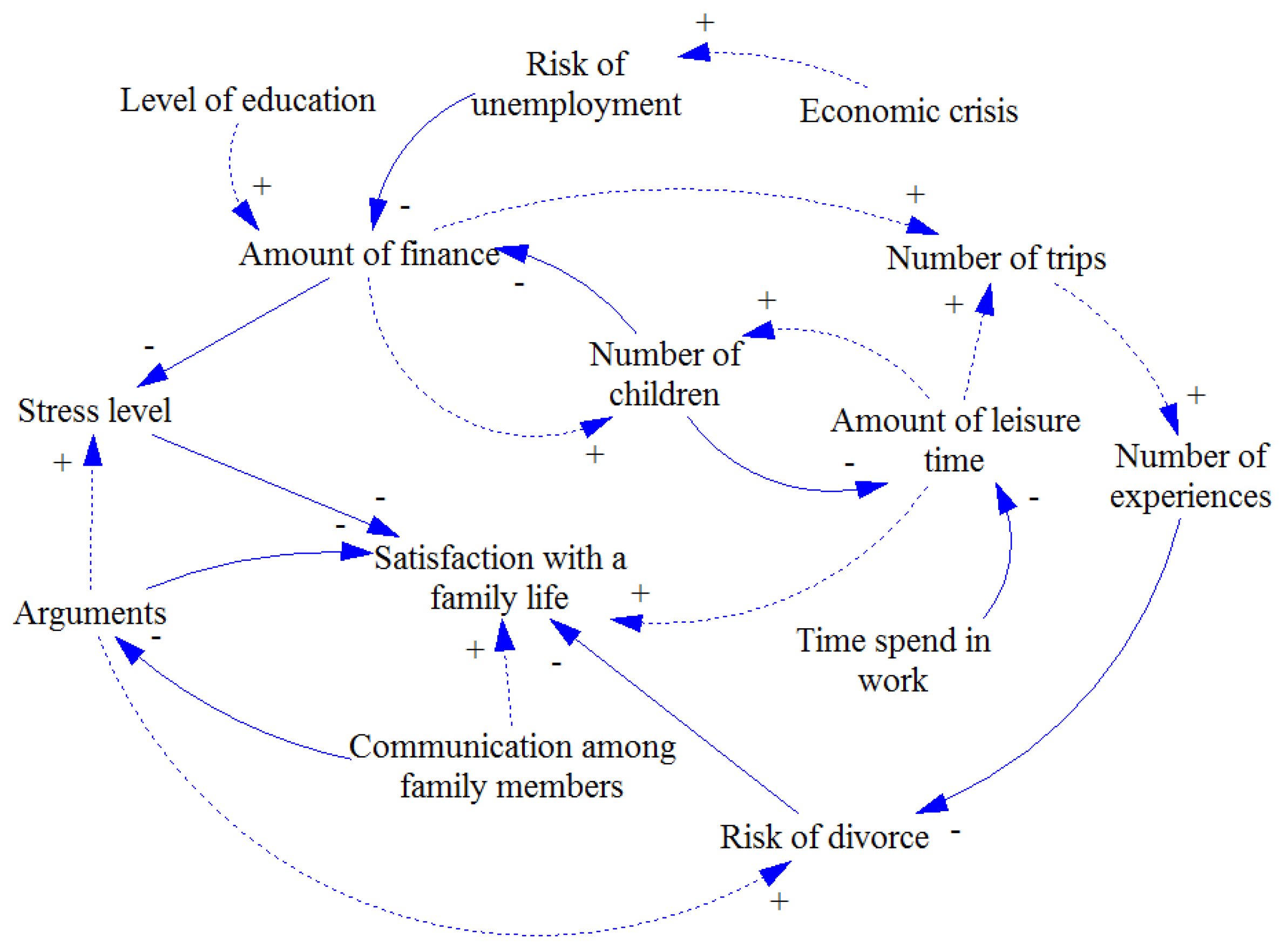
A causal loop diagram (CLD) is a causal diagram that aids in visualizing how different variables in a system are interrelated. The diagram consists of a set of nodes and edges. Nodes represent the variables and edges are the links that represent a connection or a relation between the two variables.

Communication loop diagram
Communication diagram is a kind of UML diagram shows interactions between objects, parts or sub-system. UML communication diagram provides similar detail as UML sequence diagram without time information. This tutorial, we are going to model the money-transfer operation of an online banking system with Visual Paradigm, to see how objects communicate with each others. 3.3.2020 · To compare is to examine how things are similar, while to contrast is to see how they differ. A compare and contrast essay therefore looks at the similarities of two or more objects, and the differences. This essay type is common at university, where lecturers frequently test your understanding by asking you to compare and contrast two theories, two methods, two … The Electromagnetic Induction Diagram is Shown Below: Faraday's Law is the equation that mathematically describes the electromagnetic induction. It states that voltage (EMF) will be induced when there is a change in the magnetic environment of a coiled wire. Many ways were discovered by Faraday for this to happen.
Communication loop diagram. Welcome to Master2Teach Step by Step Guide In this video, you're going to learn1. What is Communication/Collaboration Diagram?2. How to draw Communication Di... Transmission Model of Communication. The transmission model of communication describes communication as a linear, one-way process in which a sender intentionally transmits a message to a receiver (Ellis & McClintock, 1990). This model focuses on the sender and message within a communication encounter. Although the receiver is included in the model, this role is viewed as more of a target or ... Forging an effective communication loop : The message is the core idea a sender wants to communicate. The sender should carefully decide upon the precise message that he wants to communicate and its purpose. He should take into consideration the context of his communication and the attitude of the receiver. Based on these factors, the sender should choose the code and the medium for ... UML Communication Diagrams Overview. Communication diagram (called collaboration diagram in UML 1.x) is a kind of UML interaction diagram which shows interactions between objects and/or parts (represented as lifelines) using sequenced messages in a free-form arrangement.. Communication diagram corresponds (i.e. could be converted to/from or replaced by) to a simple sequence diagram without ...
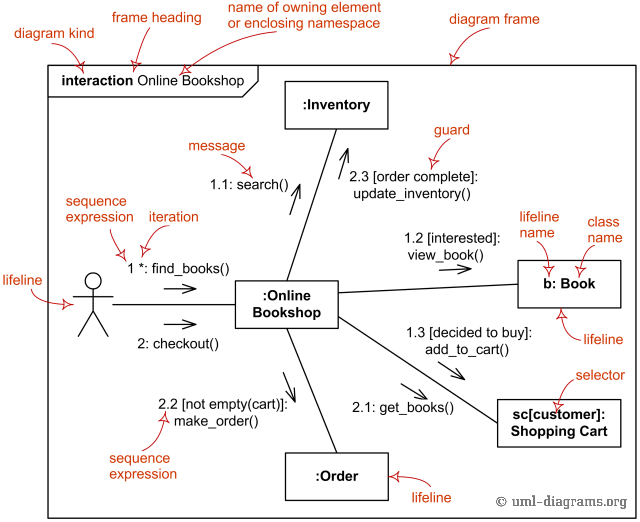
Notation Description; Frame Interaction frame for communication diagram BuyItem.. Communication diagrams could be shown within a rectangular frame with the name in a compartment in the upper left corner.. There is no specific long form name for communication diagrams heading types. The long form name interaction (used for interaction diagrams in general) could be used. 17.12.2020 · The following block diagram represents a client application that initiates a connection to a remote server with TCP Open Connection. The server, or daemon, listens for remote connections and responds appropriately. LabVIEW users can develop custom applications for TCP/IP communication. 24.8.2017 · Ans- i am a student of juet guna, doing b tech from ECE branch, i am doing my final year project with the same topic i.e. “gsm based e-notice board”. we are done with microcontroller and lcd interfacing, but now for the other segment of the project i.e. gsm and controller interface we are facing some problem. the problem is we are using the same software keil for … Given the following sequence diagram, how to express the equivalent in a UML communication diagram? Edit This is slightly different from How to express loops in Communication Diagrams? because there are two messages in the loop.
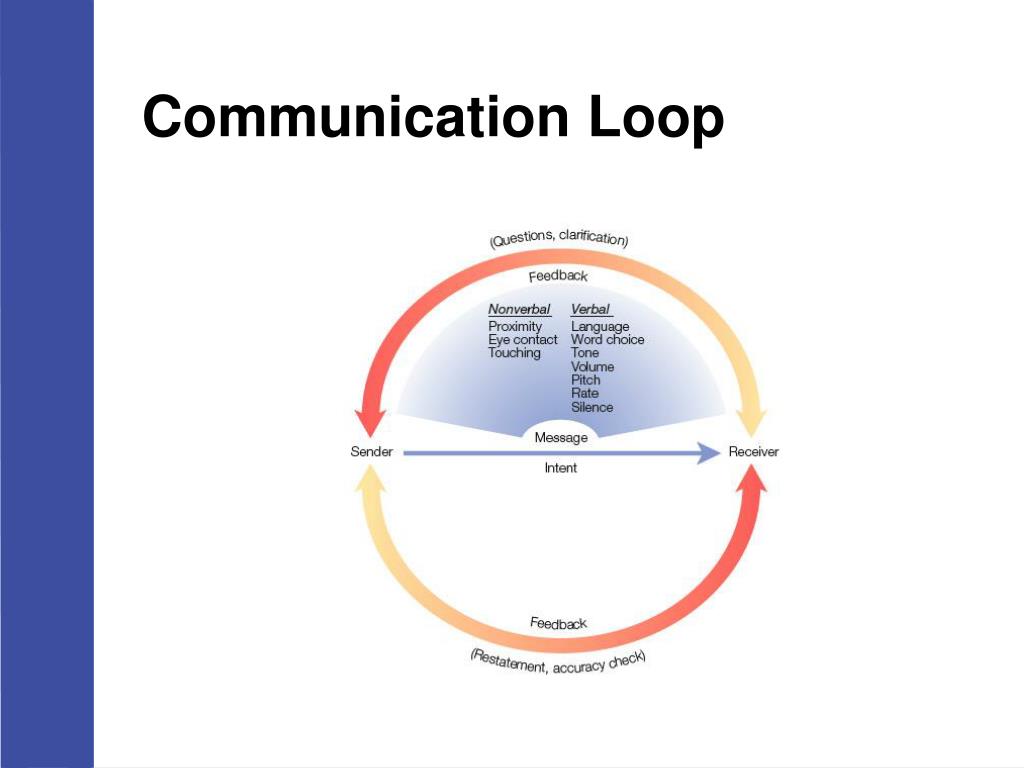
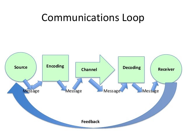
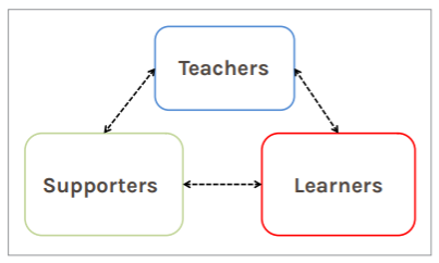
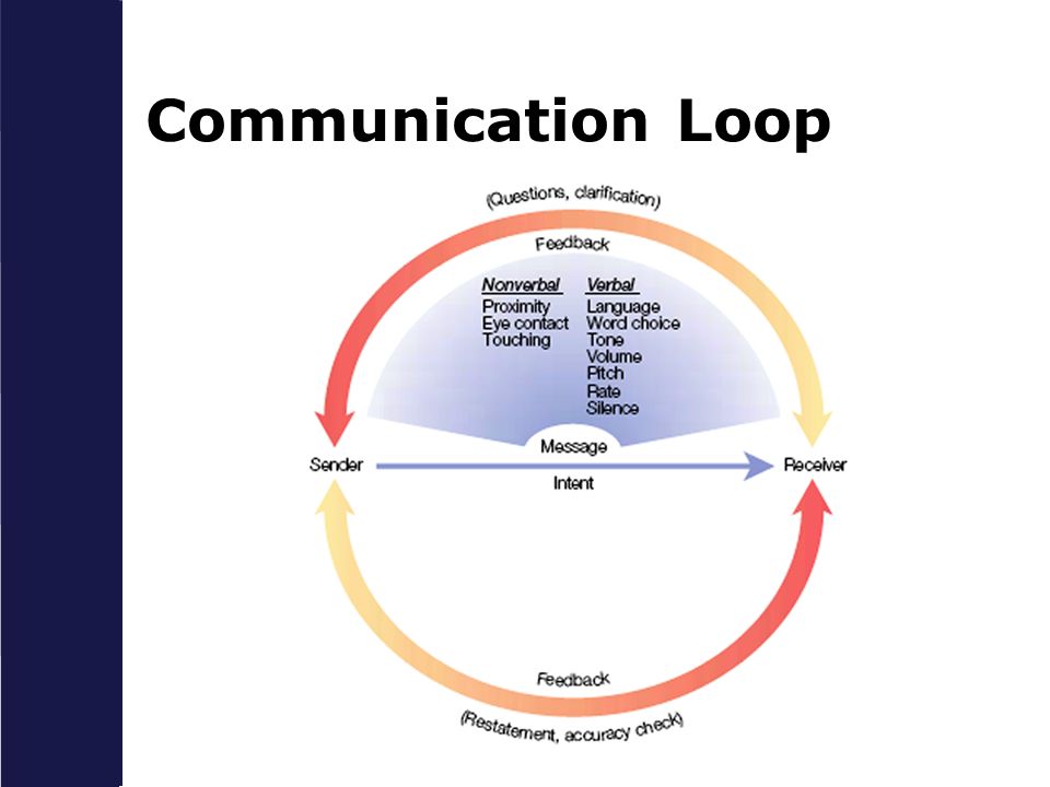
UML communication diagrams, like the sequence diagrams - a kind of interaction diagram, shows how objects interact. A communication diagram is an extension of object diagram that shows the objects along with the messages that travel from one to another. In addition to the associations among objects, communication diagram shows the messages the objects send each other. Communication is about transmitting messages between the sender and the receiver. The communication loop that we are going to describe here, is universally acceptable in that it applies equally well to all forms of communication – verbal and non-verbal, direct and indirect, and written and oral.Here’s more on the steps or phases involved in a communication loop diagram. This process is called The Communication Loop. Step 1: The Sender Encodes the Message. The Sender encodes when she takes the idea she wants to communicate and puts that idea into words, gestures, or symbols that can be understood by her Receiver. Encoding occurs every day, all the time, and very, very quickly (almost thoughtlessly). discrete loop would have a value of 120VAC (on) or 0 VAC (off) - but a value of 50 VAC would be invalid. In an analog loop, however, the signal is acceptable when it is anywhere within the stated range. For example, in a 1 to 5 VDC loop, a value of 3.3 VDC, or any other value between and including 1 to 5 VDC, would be a valid signal.
How To Become An Effective Communicator The Communication Loop Life At Leggett
Communication diagrams focus on communicating objects, which send certain messages to each other. These diagrams are not useful for modeling loops, because they depict only what kind of messages is sent and in which order. However if you use communication diagram for a good purpose and just want to include loop you have in your code, you should follow elysiums advice, but bear in mind, that ...
Uml Communication Diagrams Overview Graphical Notations For Lifeline Message Etc
ADVERTISEMENTS: The Backbone of International Business is Communication, Let us now Discuss in Detail with the help of communication flowchart:- 1. Introduction to Communication 2. Functions of Communication 3. Meaning 4. The Need Factor 5. Effective Communication 6. Assumptions and Perceptions 7. Elements 8. The Communication and Mis-Communication 9. Two Way Process and Other Details. […]

How To Write An Effective Communication Plan Asana
This relationship is indicated with a link 'loop'. Of course, the message it sends to itself is still numbered so you can see in which order all of the messages are sent. UML communication diagrams only show messages. UML communication diagrams are clearly much simpler than sequence diagrams - they help you focus on the function calls ...
Types Of
24.9.2021 · (Find an example sequence diagram with an option fragment in the Sequence Diagram Templates and Examples section). Loops . Loop fragment is used to represent a repetitive sequence. Place the words ‘loop’ in the name box and the guard condition near the top left corner of the frame.

Rt Inter Process Communication
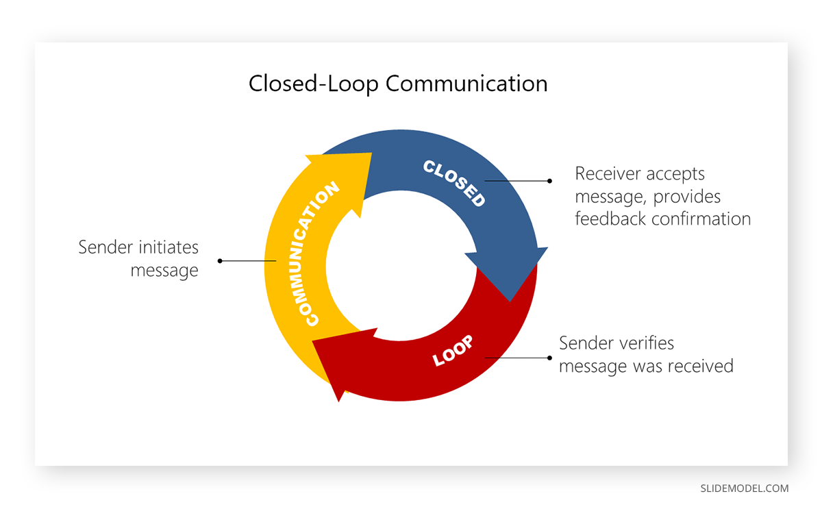
Closed-loop communication is a technique that reduces the risk of errors arising from misunderstandings and wrong assumptions. As shown in Fig 1 (attached), both the sender and receiver confirm that the information has been correctly passed on and understood. It is a good idea for team leaders to use closed-loop communication in their communication with the team. This role modelling will ...

Cybernetics Wikipedia
Instrument loop diagram (ILD) represents a connection from the field instrument to Control Room. (vice versa) Instrument loop diagram is divided into two basic sections. One is the field side and other is Control Room side. (vice versa) Fieldside is again divided into field area and Junction box.
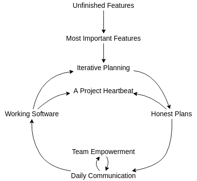
Software Production Causal Loop Diagram Template
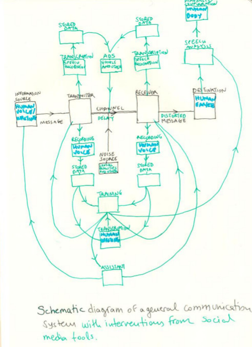
Communication Systems. The communication system is a system which describes the information exchange between two points. The process of transmission and reception of information is called communication. The major elements of communication are the Transmitter of information, Channel or medium of communication and the Receiver of information.
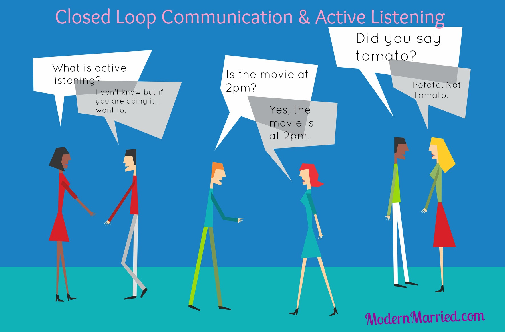
Closed Loop Communication And Active Listening Can A Cruise Ship Save Your Marriage
17.7.2021 · I2C A4 (SDA) and A5 (SCA): Used for IIC communication using Wire library. AREF: Used to provide reference voltage for analog inputs with analogReference() function. Reset Pin: Making this pin LOW, resets the microcontroller. These special functions and their respective pins are illustrated in the Arduino Nano pinout diagram shown above.
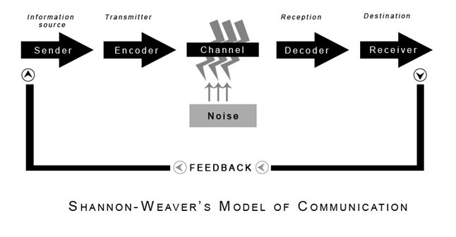
Shannon And Weaver Model Of Communication
The Communications Loop (see diagram) is a critical part of every single flight. It is virtually impossible to engage in any flight activity, from general aviation to military tactical flying, without the use of some degree of communication.
Ppt Chapter 7 Powerpoint Presentation Free Download Id 341288
Loop Diagram. In below picture a sample loop drawing is shown. Decoding the Information. ISA 5.4 clearly states minimum and optional information that should be in Loop Diagram but let's try to understand that using above loop diagram as an example.
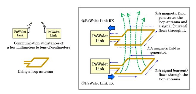
Panasonic Develops World S First Near Field Communication Technology Using Wavelet Ofdm Headquarters News Panasonic Newsroom Global
The process ends in a feedback loop, where the feedback you receive can help you to further improve your communications going forward. Note . There are many different communication process models in existence. The one we’ll look at is the most widely used and the first one published, known as the Shannon-Weaver model. It was developed by Claude Elwood Shannon and published with an ...
Systems Free Full Text A Method For Simplification Of Complex Group Causal Loop Diagrams Based On Endogenisation Encapsulation And Order Oriented Reduction
Loop diagrams are the most detailed form of diagrams for a control system and thus it must contain all details omitted by PFDs and P&IDs alike. Loop drawings can be customized per customer taste although certain minimum standard information is required to be included in loop sheets. However, the more detail you put into a loop diagram, the ...

Communication Loop Channel Between Source And Receiver Presentation Graphics Presentation Powerpoint Example Slide Templates
Home Temperature Control As shown below (click for a large view), the home heating control system described in this article can be organized as a traditional control loop block diagram.Block diagrams help us visualize the components of a loop and see how the pieces are connected. A home heating system is simple on/off control with many of the components contained in a small box mounted on our ...

Communication Loop Slide Team
A Communication Diagram in UML visually represents the components of a system along with the interactions or messages exchanged between the object. It also shows the sequence of the messaging process; however, it is not similar to the interaction diagram entirely. A communication diagram is an extension of an object diagram as it shows messages exchange along with the objects.

Communication Loop Slide Team
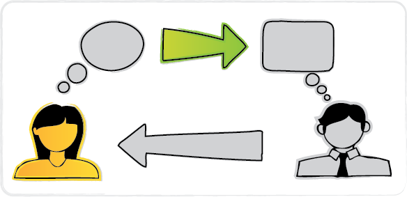
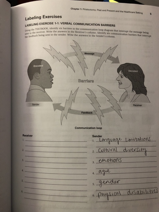
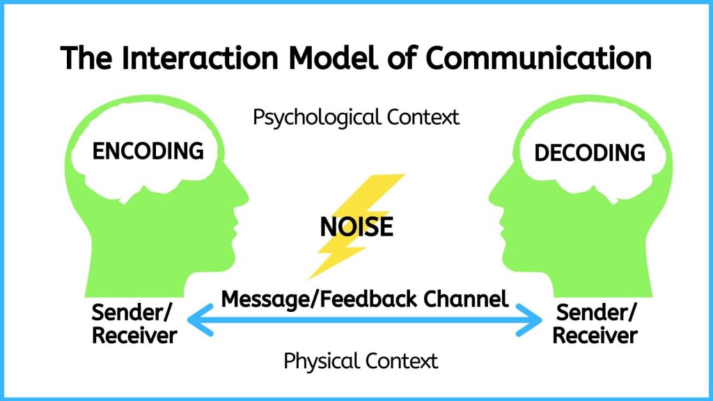
ADVERTISEMENTS: This article throws light upon the five main processes of communication. The processes are: 1. Sender 2. Transmission 3. Noise 4. Receiver 5. Feedback. Process # 1. Sender: Communication starts with the sender, who is the initiator of the message. After generating an idea, the sender encodes it in a way that can be […]
Solved Chapter 1 Phlebotomy Past And Present And The Chegg Com
A communication diagram offers the same information as a sequence diagram, but while a sequence diagram emphasizes the time and order of events, a communication diagram emphasizes the messages exchanged between objects in an application.Sequence diagrams can fall short of offering the "big picture." This is where communication diagrams come in and offer that broader perspective within a process.
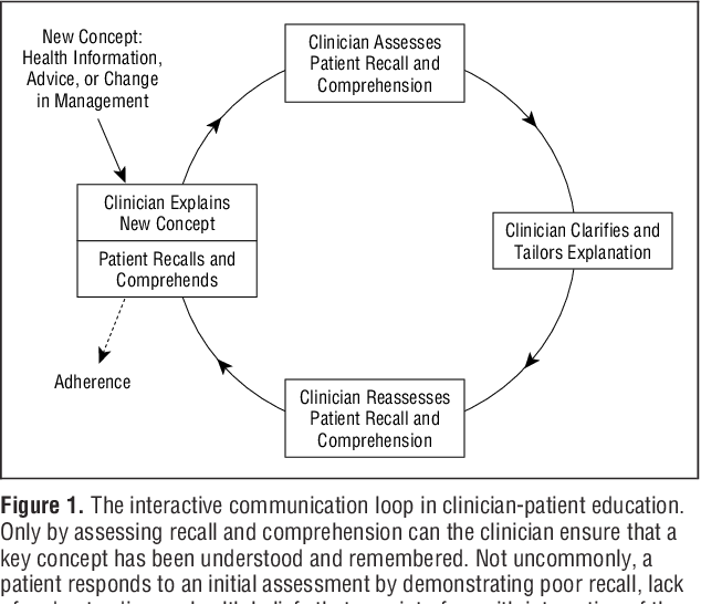
Figure 1 From Closing The Loop Physician Communication With Diabetic Patients Who Have Low Health Literacy Semantic Scholar
Fig.1 shows the block diagram of a general communication system, in which the different functional elements are represented by blocks. Fig 1. Please subscribe to Electronics Post Channel if you like my tutorials. The essential components of a communication system are information source, input transducer, transmitter, communication channel ...
Isis Papyrus Business Apps Adaptive Case Management
Discussing communication in terms of sender-receiver implies one-way communication. However, human communication often is a two-way process in which each party shares sending and receiving responsibilities. As the quantity of people taking part in a communication increases, the potential for errors in encoding and decoding increases,
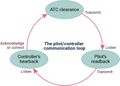
Failure To Communicate Flight Safety Foundation
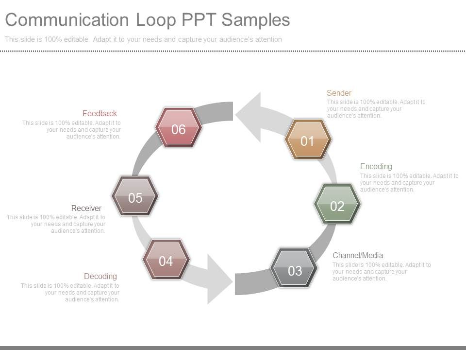
Presenting custom communication loop diagram ppt templates. This is a communication loop diagram ppt templates. This is a five stage process. The stages in this ...

What Is The Plan For Continued Communication Throughout The Renovation Project Stevenson Hall Renovation Project At Sonoma State University
4, ENCODING, CHANNEL/ MEDIA, DECODING. 5. 6. 7. 8. 9. 10. 11, SENDER, RECEIVER. 12. 13, COMMUNICATION LOOP DIAGRAM. 14. 15. 16. 17, FEEDBACK. 18. 19. 20. 21.

Representing Loops In A Uml Communication Diagram Stack Overflow
3 hours ago A causal loop diagram (CLD) is a causal diagram that aids in visualizing how different variables in a system are interrelated. The diagram consists ...

Communication Workflow Cycle With Feedback Loop Ppt Powerpoint Presentation Model Show Pdf Powerpoint Templates
The Electromagnetic Induction Diagram is Shown Below: Faraday's Law is the equation that mathematically describes the electromagnetic induction. It states that voltage (EMF) will be induced when there is a change in the magnetic environment of a coiled wire. Many ways were discovered by Faraday for this to happen.

Closing The Loop On Communication
3.3.2020 · To compare is to examine how things are similar, while to contrast is to see how they differ. A compare and contrast essay therefore looks at the similarities of two or more objects, and the differences. This essay type is common at university, where lecturers frequently test your understanding by asking you to compare and contrast two theories, two methods, two …

The Two Way Communication Loop Download Scientific Diagram
Communication diagram is a kind of UML diagram shows interactions between objects, parts or sub-system. UML communication diagram provides similar detail as UML sequence diagram without time information. This tutorial, we are going to model the money-transfer operation of an online banking system with Visual Paradigm, to see how objects communicate with each others.

The Process Of Communication Organizational Behavior And Human Relations
Rotating Arrow Communication Loop Message Icon Presentation Graphics Presentation Powerpoint Example Slide Templates

What Is Two Way Communication Definition Systems Examples Video Lesson Transcript Study Com

Communication Process Communication Process Effective Communication Skills Essay Writing Skills

Causal Loop Diagram Domain Vithanco

Vector Business Illustration Of Technology Service Communication Loop Infinity Stock Illustration Download Image Now Istock
Interaction Of Model Of Communication Introduction To Communication In Nursing

Building Remote Relationships And The Broken Virtual Communication Loop

Use Feedback To Complete The Communication Cycle
Communication
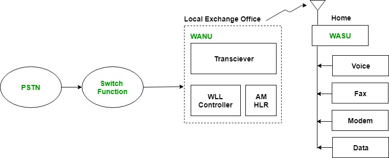
Wireless Local Loop Geeksforgeeks
Closed Loop Communication Diagram Powerpoint Slide Slidemodel
Knowatom S Blog Insights To Stem Curriculum Ngss Closed Loop Communication
Chapter 6 Communication And Conflict Resolution Chapter Outline Verbal And Nonverbal Communication Nonverbal Communication Gender Differences In Ppt Download

Shannon S Diagram Expanded To A Circular Communication Loop Between Two Download Scientific Diagram
User Angeliki Grad Project Loop Media Design Networked Lens Based Wiki
Communication Loop Ppt Samples Powerpoint Presentation Templates Ppt Template Themes Powerpoint Presentation Portfolio


Comments
Post a Comment