42 instrument loop diagram
When a loop diagram shows you exactly what wire color to expect at exactly what point in an instrumentation system, and exactly what terminal that wire should connect to, it becomes much easier to proceed with any troubleshooting, calibration, or upgrade task. Loop diagrams are fairly constrained in their layout as per the ISA 5.1 standard. Instrument Loop diagram basics. May 19, 2021. June 5, 2021. 4instrumentation20. The loop diagram is the document consist of all connections of instruments from the field to the control panel. It displays the detail of the loop by which it is helpful during the commissioning and maintenance activities. It very useful in spotting the terminal ...
In this lesson we go over the ever important and go to document as an Instrument technician and that is the Loop diagram. We talk about what they are, how th...
Instrument loop diagram
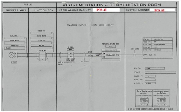
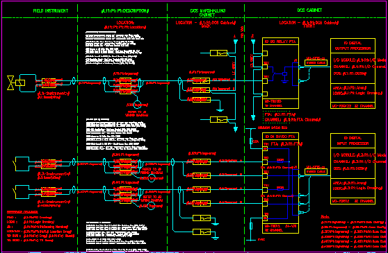
Instrument loop diagram (ILD) represents a connection from the field instrument to Control Room. (vice versa) Instrument loop diagram is divided into two basic sections. One is the field side and other is Control Room side. (vice versa) Fieldside is again divided into field area and Junction box. D3060/F1050 - Appendix F, Instrument Loop Diagrams Guidance Rev. 1, 10/27/06 1.0 PURPOSE AND SCOPE Application of ISA-5.4-1991, Instrument Loop Diagrams, is required for safety-related instrumentation systems (ESM Chapter 8 Section 3.4). This appendix provides additional guidance in the preparation and use of instrument loop diagrams. A loop diagram has a logical method to help you read and interpret information. ISA standard discusses the preparation and use of diagrams for instrument loops. A loop diagram shows you how the instruments are arranged in the loop.From the loop diagram you can identify the connections between devices and the communication path.
Instrument loop diagram. Instrumentation Loop Diagrams CAD & Drafting Standards Manual 11-7 May 11, 2015 11.3.2 Drawing Content Instrument Loop Diagrams will accurately record all field conditions. ILDs shall contain all of the following information relevant to the loop: • A Loop Tag Number is always required. All field and drawing tagging must agree with the P&IDs. As a minimum, an instrument loop diagram shall contain the information covered below. 1) Identification of the loop and loop components shown on the P&IDS. Other principal components of the loop to be shown and identified under ISA-5.1, "Instrumentation Symbols and Identification". 2) Word description of loop functions within the title. 1. Read P&IDs (process and instrumentation diagrams). 2. Read instrument loop diagrams. 3. To be able to install and calibrate basic instruments. 4. Apply basic instrumentation to control an industrial process. 5. Apply simple design of control loops used in processes. 6. Understand feedback, feedfoward, cascade and ratio control. Instrument loop diagrams are also called instrument loop drawings or loop sheets. These set of drawings are more detailed than process and instrument diagrams (P&IDs). Loop diagrams are the most detailed form of diagrams for a control system and thus it must contain all details omitted by PFDs and P&IDs alike.
Instrumentation and Loop Diagram Software. A new "data-centric" Instrument design and documentation system. Used for the automated production of instrumentation documents such as, Instrument Data Sheets, Loop Diagrams, Hook up Diagrams, Wiring /Terminal Strip diagrams, Instrument Index report, Bill of materials report, Cables Schedule report, Interconnection reports and many other documents. Instrument Loop Diagram is a drawing that showing detail information of how a loop is connected.This document is common in oil and gas industry. Instrument loop diagrams. The Loop Diagrams extend the P&IDs, they show the components of the instrument loop, connections between devices and identification of component action, the specification of instrument hardware items and a means of communicating requirements. Loop diagrams can be specified according to customer and project requirements. Instrument Loop Diagrams are used for this purpose. Instruments loop diagrams will provide more specific information about the loop. One may also ask, what is loop testing in instrumentation? Loop checking is the process that confirms the components wired correctly and also helps to ensure that the system is functioning as designed.
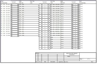
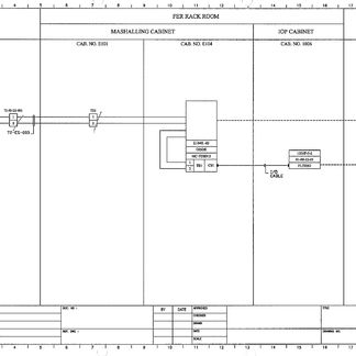
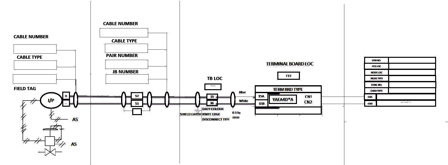
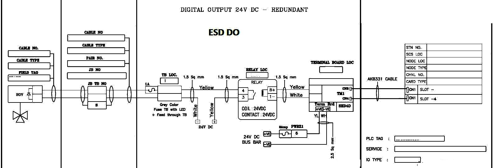
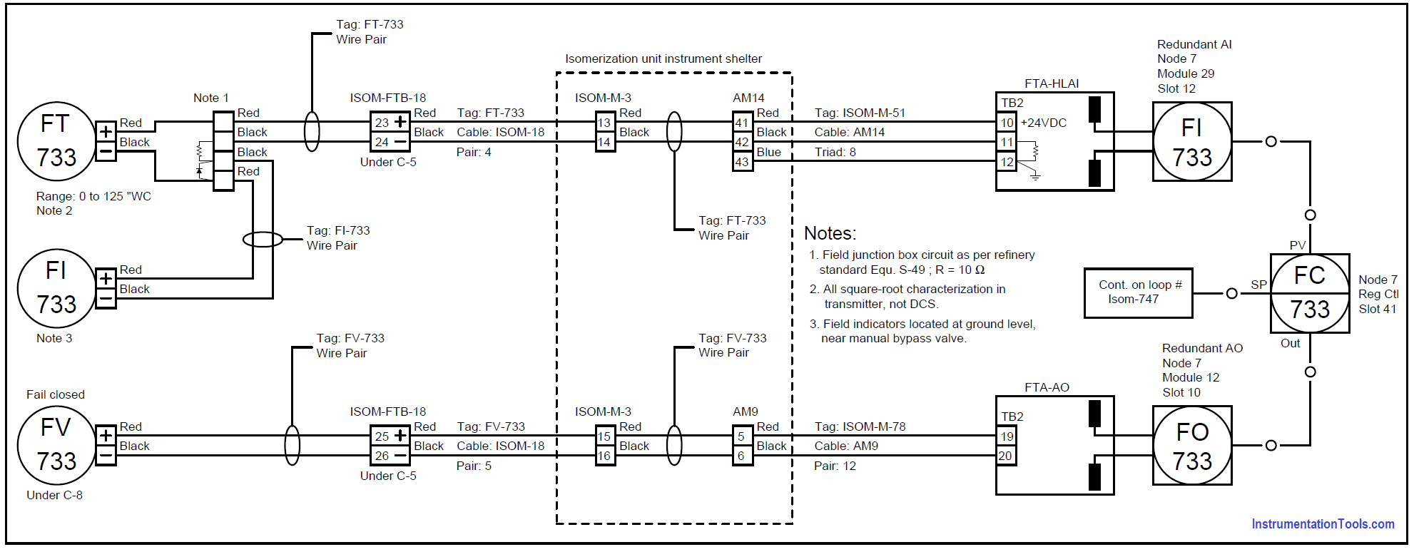
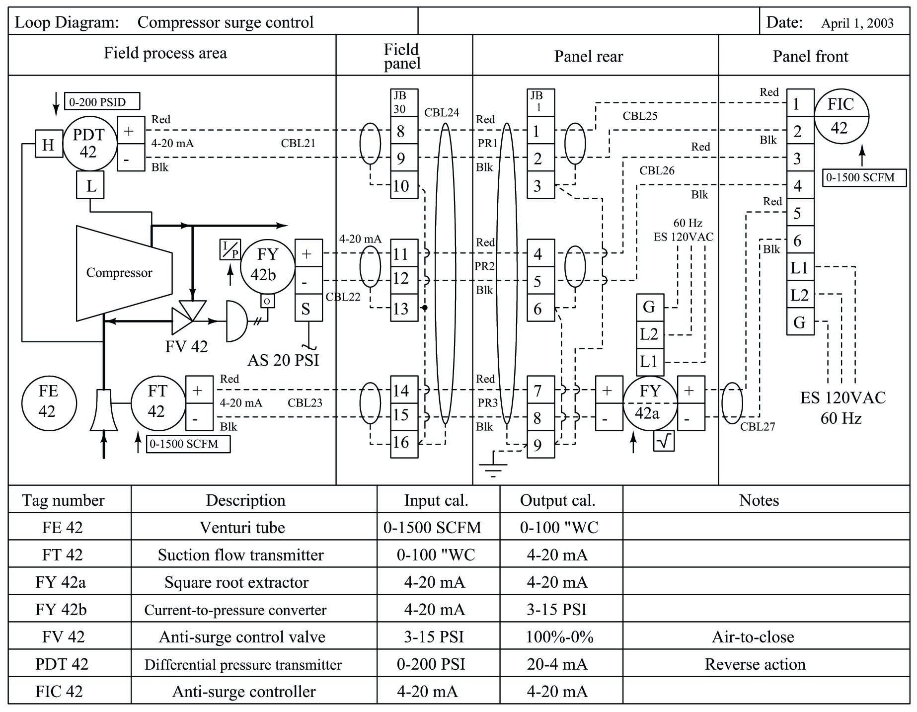
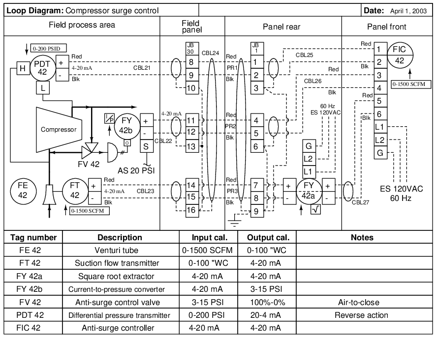
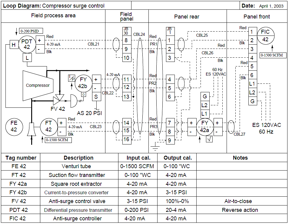
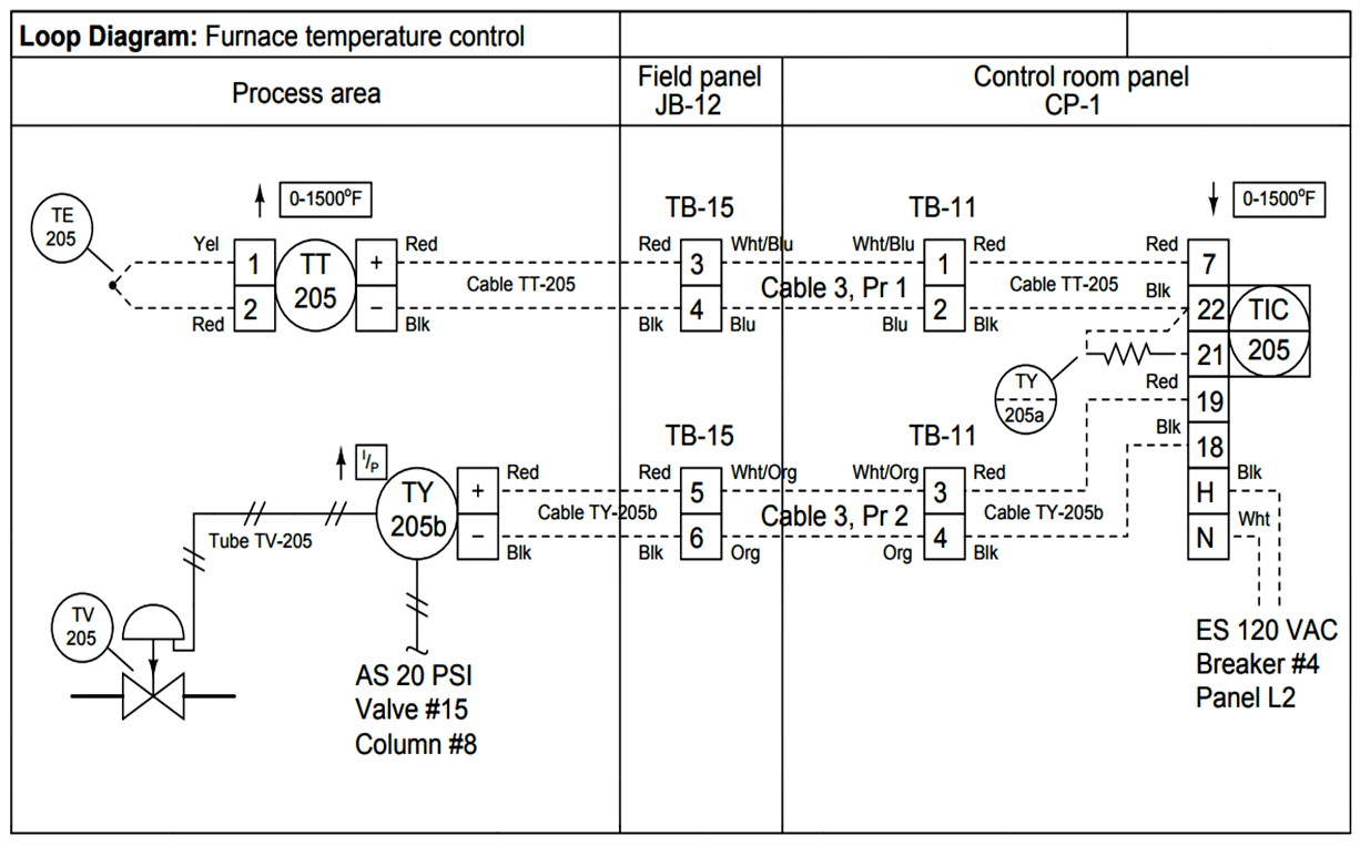
Loop diagram shows instrument (in a symbol) and its terminal numbers which are to be connected, instrument cable number, junction box number, terminal number assigned for the specified instrument, multi-pair cable and pair number , marshalling cabinet number, terminal number in marshalling cabinet, control system details (rack, slot, I/O ... In above loop diagram temperature element wiring to its transmitter is also shown with transmitter's terminal numbers and colours of the cables. But Instrument range is also indicated above the transmitter, which is not compulsory or something should be mentioned in each loop diagram. Every loop diagram's format would be different in some ... Instrument loop diagrams are also called instrument loop drawings or loop sheets. These set of drawings are more detailed than process and instrument diagrams (P&IDs). Each instrument bubble in a loop diagram represent an individual device with its own terminals for connecting wires. Instrument loop diagram represents detailed drawing showing a connection from one point to control system.Loop diagram shows instrument (in a symbol) and its...
Wiring Diagram And Loop Drawing Conversion For Spi
Converting Instrument Loop Diagrams to CAD. Here's how you can convert Instrument Loop Diagrams (ILDs) to CAD using Scan2CAD. Launch Scan2CAD and import the high-quality raster Instrument Loop Diagram you wish to convert to CAD. Click the Clean image button to clean the drawing. Notably, even though you may have selected a high-quality ILD ...

Instrument Technician E I Instrument Loop Diagram Ild Represents A Connection From Field Instrument To Control Room Vice Versa Instrument Loop Diagram Is Divided In To Two Basic Sections One Is Field Side And
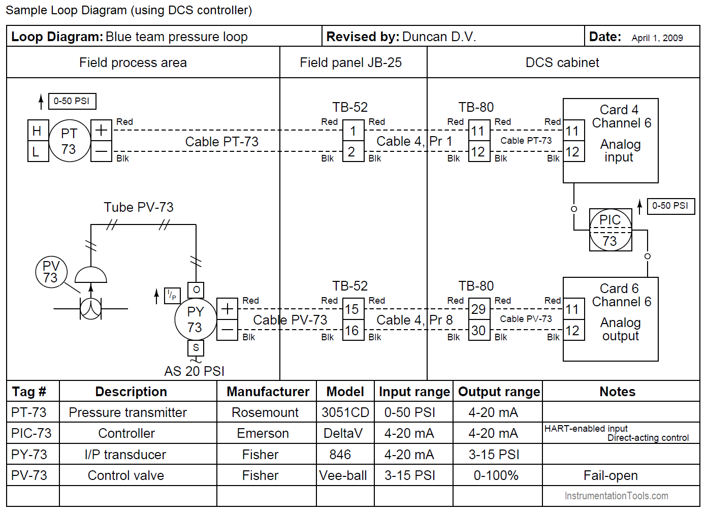
Loop Diagram helps us to read the wiring connections from field instruments to system cabinet. Find the top 15 Loop Diagram Questions here. Read: What are Loop DIagrams? Examine this loop diagram, and answer the following questions: Loop Diagram. Click on the image to zoom

Instrumentation Loop Diagrams Instrumentationtools Diagram Loop
The only type of diagram for this system more detailed than a loop diagram would be an electronic schematic diagram for an individual instrument, which of course would only show details pertaining to that one instrument. Thus, the loop diagram is the most detailed form of diagram for a control system as a whole, and as such it must contain all ...
How To Create Instrument Loop Diagram Marshalling Loop Diagrams
GENERATION OF INSTRUMENT LOOP DIAGRAM USING EXCEL MACRO'S. Dear all, I am working on a project where I need to generate loop diagram for instruments. But in my case the number of instruments is more than 1000. The advantage here is, the template for typical type of instruments are the same and its about matter of few data's to be changed (Eg.

Automatic Instrument Loop Diagram Creation Cadline Community
activating the control system to produce the output. The two general classifications are open-loop and closed-loop control systems. An open-loop control system is Figure 1 Open-Loop Control System one in which the control action is independent of the output. An example of an open-loop control system is a chemical addition pump with a variable ...
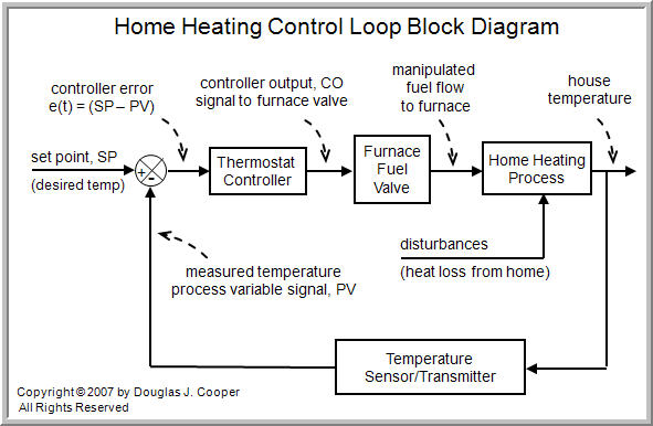
The Components Of A Control Loop Control Guru
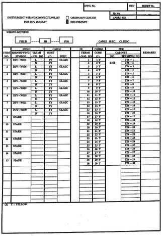
instrument loop diagram instrument logic diagram instrument location drawing instrument loop testing check report instrument loop and tag index list esd block & logic diagram punch list. loop folder contents test/cover sheet area loop number service description associated instrument tag pre-witness loop check to be signed by contractor qa/qc

What Is Block Flow Diagram
This is a video that describes in detail how to read an Instrument Loop Diagram. This is useful in teaching instrumentation technicians and drafters.
Nikolay Bozov Industrial Automation And Control
Instrument Loop Diagrams are used for this purpose. Instruments loop diagrams will provide more specific information about the loop. what is a loop sheet? Instrument loop diagrams are also called instrument loop drawings or loop sheets. These set of drawings are more detailed than process and instrument diagrams (P&IDs).
Wiring Diagram And Loop Drawing Conversion For Spi
The instrument loop diagram is a composite representation of instrument loop information. It contains all associated electrical and piping connections and should contain all of the information needed to accommodate the intended uses. Classified below are minimum require- ments and some established options that can be used to match the desired uses.

Sample Of Works
The different types of instrumentation diagrams which are commonly used are (i) process flow diagram (PFD), (ii) loop diagrams (loop sheets), (iii) process and instrument diagrams (P&ID), and (iv) functional diagrams. At the highest level, the interest is in the interconnections of process vessels, pipes, and flow paths of process fluids.

Analog Input Complete Loop Drawing Instrument Guru Youtube
Figure 5.19 illustrates a combination of the instrumentation group and type to develop symbols and abbreviations that represent an instrument's function on a flow diagram. The first letter in the symbol typically indicates the process variable (pressure, level, temperature, or flow), while the second and/or third letter indicates the instrument ...

How To Create Instrument Loop Diagram Marshalling Loop Diagrams
A loop diagram has a logical method to help you read and interpret information. ISA standard discusses the preparation and use of diagrams for instrument loops. A loop diagram shows you how the instruments are arranged in the loop.From the loop diagram you can identify the connections between devices and the communication path.

Piping And Instrument Diagram Of The Industrial Closed Loop Process Download Scientific Diagram
D3060/F1050 - Appendix F, Instrument Loop Diagrams Guidance Rev. 1, 10/27/06 1.0 PURPOSE AND SCOPE Application of ISA-5.4-1991, Instrument Loop Diagrams, is required for safety-related instrumentation systems (ESM Chapter 8 Section 3.4). This appendix provides additional guidance in the preparation and use of instrument loop diagrams.

Calibration Of Temperature Switch
Instrument loop diagram (ILD) represents a connection from the field instrument to Control Room. (vice versa) Instrument loop diagram is divided into two basic sections. One is the field side and other is Control Room side. (vice versa) Fieldside is again divided into field area and Junction box.
What Is Instrument Loop Diagrams Dcs Instrumentation Forum
Instrument Loop Diagrams Kishore Koduvayur
How To Convert Instrument Loop Diagrams Ild To Cad Scan2cad

How To Create Instrument Loop Diagram Marshalling Loop Diagrams Diagram Loop Organisation Name

Instrument Loop Diagram Youtube
What Is Instrument Loop Diagrams Dcs Instrumentation Forum
Ild Instrument Loop Diagram By Acronymsandslang Com
Instrument Manager Customisation Custom Loop Templates
Wiring Diagram And Loop Drawing Conversion For Spi
15 Loop Diagram Questions Instrumentation Tools
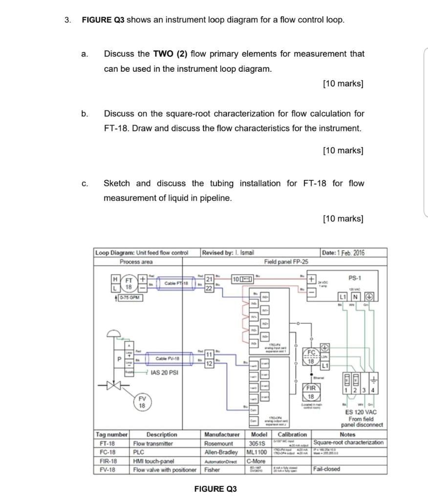
Solved 3 Figure Q3 Shows An Instrument Loop Diagram For A Chegg Com
1
Nikolay Bozov Industrial Automation And Control

Loop Drawings For Smart Instruments

Instrumentation Loop Sheet Youtube
About Protective Instrument Loops
Loop Diagrams Loop Sheets Control And Instrumentation Documentation Automation Textbook

Basics Of Instrument Loop Diagrams Learning Instrumentation And Control Engineering
Control Systems Mcburney
7 3 Loop Diagrams Instrumentation Documents

Loop Checking Procedure Instrumentation And Control Engineering

Basics Of Instrument Loop Diagrams Learning Instrumentation And Control Engineering
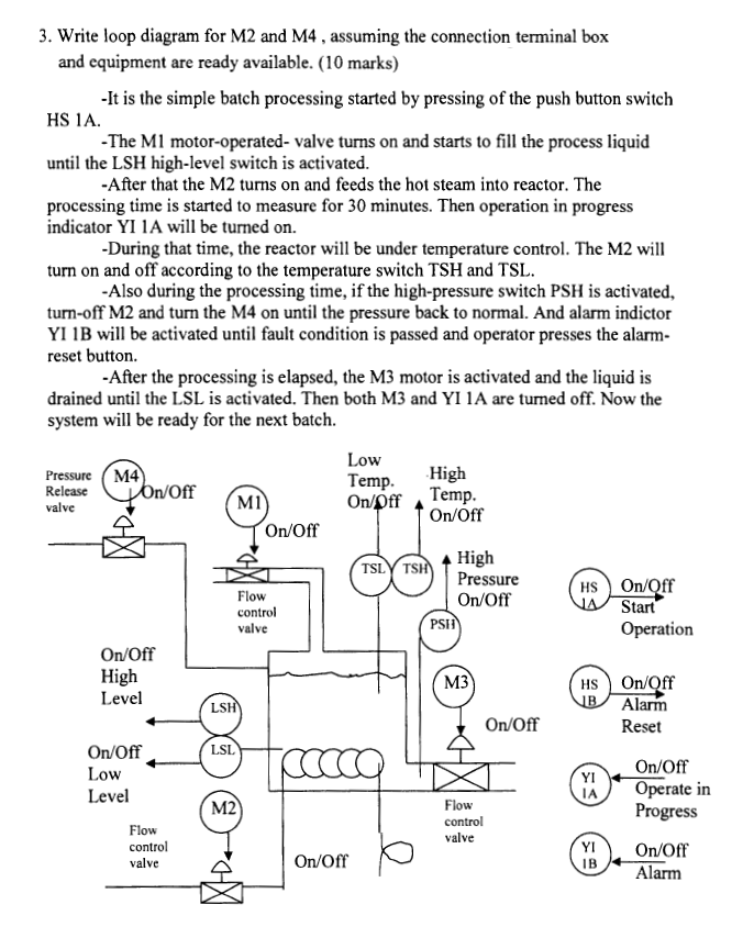
3 Write Loop Diagram For M2 And M4 Assuming The Chegg Com

Instrument Loop Diagrams Online Training Course Training From Dss

What Is An Instrumentation Loop Diagram Field Instrumentation Industrial Automation Plc Programming Scada Pid Control System
1
Instrumentation Loop Diagrams Instrumentationtools
Purpose Of Loop Diagrams Instrumentation Design


Comments
Post a Comment