42 arcade button wiring diagram
Arcade Game Manual for Police Trainer, an arcade game by P and P Marketing, Inc. Includes parts list, set up instructions, test menu instructions, pin out diagram, wiring diagram and io schematic diagram. Part no. 780-8000-00. From P and P Marketing, Inc. 4520 W. Dickens Avenue, Chicago, Illinois 60639. (773)292-4540. Dec 15, 2020 · Led Arcade Button Wiring Diagram. Print the electrical wiring diagram off and use highlighters to trace the signal. When you employ your finger or follow the circuit together with your eyes, it is easy to mistrace the circuit. One trick that I use is to print the same wiring diagram off twice.
Button connectors should be clear now. LED: start with 1k resistor (current will be ca. (5V-1,6V)/1k = 3mA - this should already light the button LED; you can then lower it down to ca. 220 Ohm (5V-1,6V)/220 = ca. 14mA; The calculation is not exact as I don't know the exact value of the LED forward voltage.

Arcade button wiring diagram
There is a color coded wiring diagram on the X-arcade site, also, BTW. The X-Arcade™ was designed to be used with a variety of games and MODE 1 (switch closest to the serial cable, or yellow wire on the switch itself) cannot be programmed. The mouse buttons on the Tankstick/trackball cannot be programmed. it (the purple female plug near the ... Mar 14, 2018 · Led arcade button wiring diagram. One of the things that made it easy to wire the buttons was the fact that i used the mot ion controller as opposed to a programmable interface board like the ipac. What ever power supply you use the principal is the same. For anything more well have to manually solder them. This is a shot of of the wiring on the Q*bert boards. Common practice would be to place all the connector with the stickers the same side up. But connector P4 off the Power supply board gets flipped over. If I would have sat down and studied the wiring diagram (like I finally did , determining my problem) I would have saved myself lots of ...
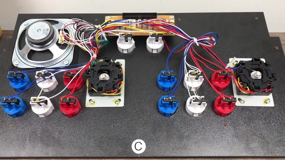
Arcade button wiring diagram. Nov 20, 2021 · There is a color coded wiring diagram on the X-arcade site, also, BTW. The X-Arcade ™ was designed to be used with a variety of games and MODE 1 (switch closest to the serial cable, or yellow wire on the switch itself) cannot be programmed. The mouse button s on the Tankstick/trackball cannot be programmed. it (the purple female plug near the ... Adafruit Industries, Unique & fun DIY electronics and kits Arcade Button with LED - 30mm Translucent Green : ID 3487 - A button is a button, and a switch is a switch, but these translucent arcade buttons are in a class of their own. Particularly because they have LEDs built right in! That's right, you'll be button-mashing amidst a wash of beautiful light with these lil' guys. They' ... Repeat this process for each potentiometer leg and arcade button leg, referring to the wiring diagram. Not every joint will be the same, so make sure you know what wire needs to go where. Don't solder anything to the bottom right most arcade button (on pin 13) as it's quite different and covered in the next section. The most common wiring setup for a microswitch is to have the ground wire on the very bottom prong (the common prong) and the action wire on the prong closest to the ground wire (the normally open prong). This will send a signal to the board whenever the button is pressed. This setup is used in the majority of arcade games that you will encounter.
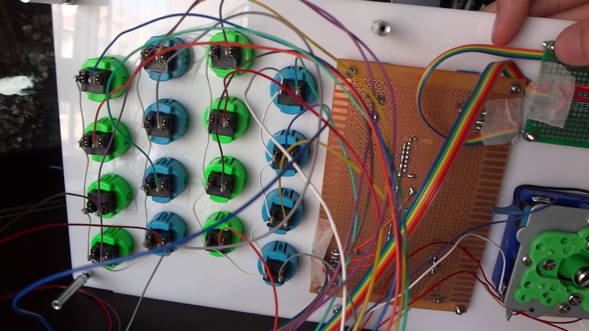
In this video we will walk through the different button layouts and a wiring basics overview for your arcade machine. There are several different layouts th... Dec 06, 2020 · Arcade Button Wiring Diagram Source: i.ytimg.com Before reading the schematic, get acquainted and understand each of the symbols. Read typically the schematic like a new roadmap. Arcade USB Encoder Wiring Guide. Oct 19, 2011. So you've just received your Zero Delay Arcade USB Encoder and its time to wire it up! Start by getting the USB Encoder PCB board and take note of the connections. We are going to wire up the Joystick first, so grab that and the ribbon cable. Plug one end of the ribbon cable into the joystick port ... Connecting Arcade Buttons to Raspberry Pi GPIO Pins. May 31, 2015/ Florian Maurer. The simplest and least expensive path is purchasing pre-made wires. Doing this saves you from having to crimp half the connections as well as needing to buy wire of each color by the spool. This guide covers trimming the wires to the length we need and adding a ...
Attach all grounding wires onto all the buttons and the Cthulhu board. Finally, connect the remaining wires from the buttons to the Cthulhu board according to the diagram. Screw the base back to the bottom and attach 4 rubber feet onto the corners of the base. Congratulations! Your arcade joystick box is finally complete! Build a daisy chained wire harness to connect to the +5v connector on your existing board. This will power the led portion of the buttons (which by the way are the other two pins on the image you included). You will need to determine which pin on the connector is power and which ground. Circuit Diagram. This provides a visual reference for wiring of the components. They aren't true to scale, just meant to be used as reference. The LEDs are embedded into the arcade button housing. They appear separate in the diagram for clarity. To power this project, we're connecting microUSB to a computer's USB port. New LED Arcade buttons, unboxing, how to wire and hook up, and lastly a brief review.Arcade LED MAME 2 Player USB Bundle Kit -- https://www.banggood.com/cust...
Usb Encoder Wiring Diagram | USB Wiring Diagram
Arcade Legends Manual Rev1.pdf. 2006-07-01 21:47. 959K. Arch Rivals Hometown Hero Options Kit.pdf. 2006-06-11 17:50. 376K. Arch Rivals Kit Installation (16-4001-K-101 May 1989).pdf.

WiFi arcade controller (x-OSC Java demo) - x-io Technologies
Sanwa Joystick Wiring Diagram. There was a Sanwa JLF Wiring Guide, but I redid this one with info for wiring a I bought the 5 pin harness and joystick from focus wiringall.com on their If you use the first diagram linked, you would just need to choose picture. This time, we will install Sanwa buttons and a Sanwa joystick to our box.
Arcade Button Wiring Diagram - Wiring Diagram Networks
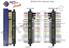
Jamma in-1 PCB, iCade, Arcade Multigame, Multicade board, JAMMA, Jamma PCB, Jamma in-1, 60 in 1, Click Here for wiring diagrams and manuals!. I want to hook up a 60 in 1 board in it for my I see the Jamma wire harness on ebay and a power supply is that all I need or do you need a.Arcade Game Part Manuals.

Wiring Diagram For Micro Switch
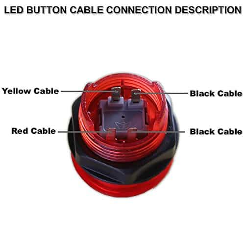
Place the arcade button through the 1" hole. Secure the arcade button by screwing the nut onto the back of the arcade button. NOTE: Screw the nut with the teeth facing the arcade button (See below) Attach the blue cables to "COM Connector 3" and "NO Connector 2" (see diagram below). Snap white plastic switch back in place.

Ms. Pacman: Custom Build project on Behance
TAMA, The Arcade Manual Archive, strives to be the Internet's premier technical manual resource for amusement industry technology. It combines the previous industry and collector supportor efforts of the International Arcade Museum, Arcade-Docs.com, and Arcade-Manuals.com. Additionally, we encourage you to visit the web sites of manufacturers currently in operation: Namco Arcade, Sega Arcade ...

X Arcade Wiring Diagram - Wiring Diagram Schemas
Great solution to connect both buttons, joysticks and led strips when using led lighting and you don't want to mess around with a arcade power supply and use a ac adapter instead. 5 Wiring For Illuminated Buttons

Project MAME - Basic Arcade and MAME joystick and push ...
Install a JAMMA Harness in an Arcade Cabinet: I have an arcade machine in a cabinet that doesn't work. I got another board, but the pins didn't match - I figured out I needed to replace the wires. I bought a JAMMA harness, but everything was in Chinese. Here's how I muddled through to …

Whilst strolling through any arcades, always stop to take a photo and play around in Lightroom. You’ll be impressed.
Harness: Ready made wiring or what you call your finished wiring Micro switch: Commonly used switch used for joystick and push buttons. Sometimes you will encounter micro switches with three legs instead of two. The illustration shows where you need to connect your wiring.

X Arcade Wiring Diagram - Wiring Diagram Schemas
I think this diagram will work for your buttons -- related thread here. The two pin / two 0.110" Quick Disconnect wires connect to the microswitch tabs. (A and B) There should also be some "daisy-chains" for the red connectors. One daisy-chain for ground like the black wire below and one daisy-chain for 5v like the red wire below.

Audio mixing table
General theory on wiring arcade switches (buttons & joysticks) Warning: This is not a terribly technical discussion. If you *really* want to understand wiring and electronics, take a look at the tutorials section on the techs & tips page, look for the electronics link. What this will attempt is a brief "how-to" on connecting up wiring to your controls.
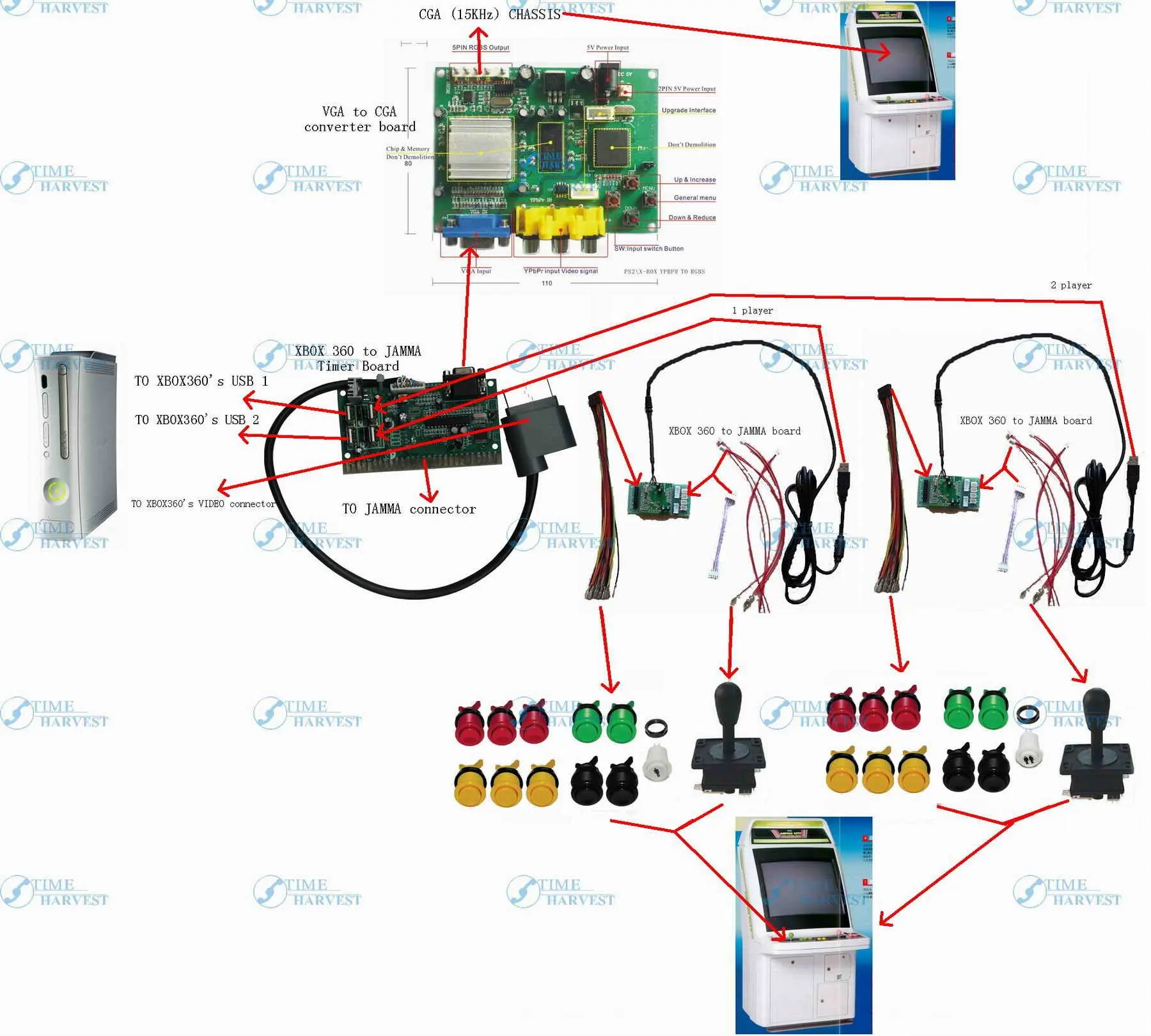
X 360 to arcade machine time board game kit with American ...
The diagram below provides a visual reference for wiring of the components. This diagram was created using the software package Fritzing. ... Arcade Button with LED - 30mm Translucent Clear. $2.50. Add to Cart. STEMMA QT / Qwiic JST SH 4-pin Cable - 100mm Long. $0.95. Add to Cart.

Arcade Button Wiring Diagram - Wiring Diagram Networks
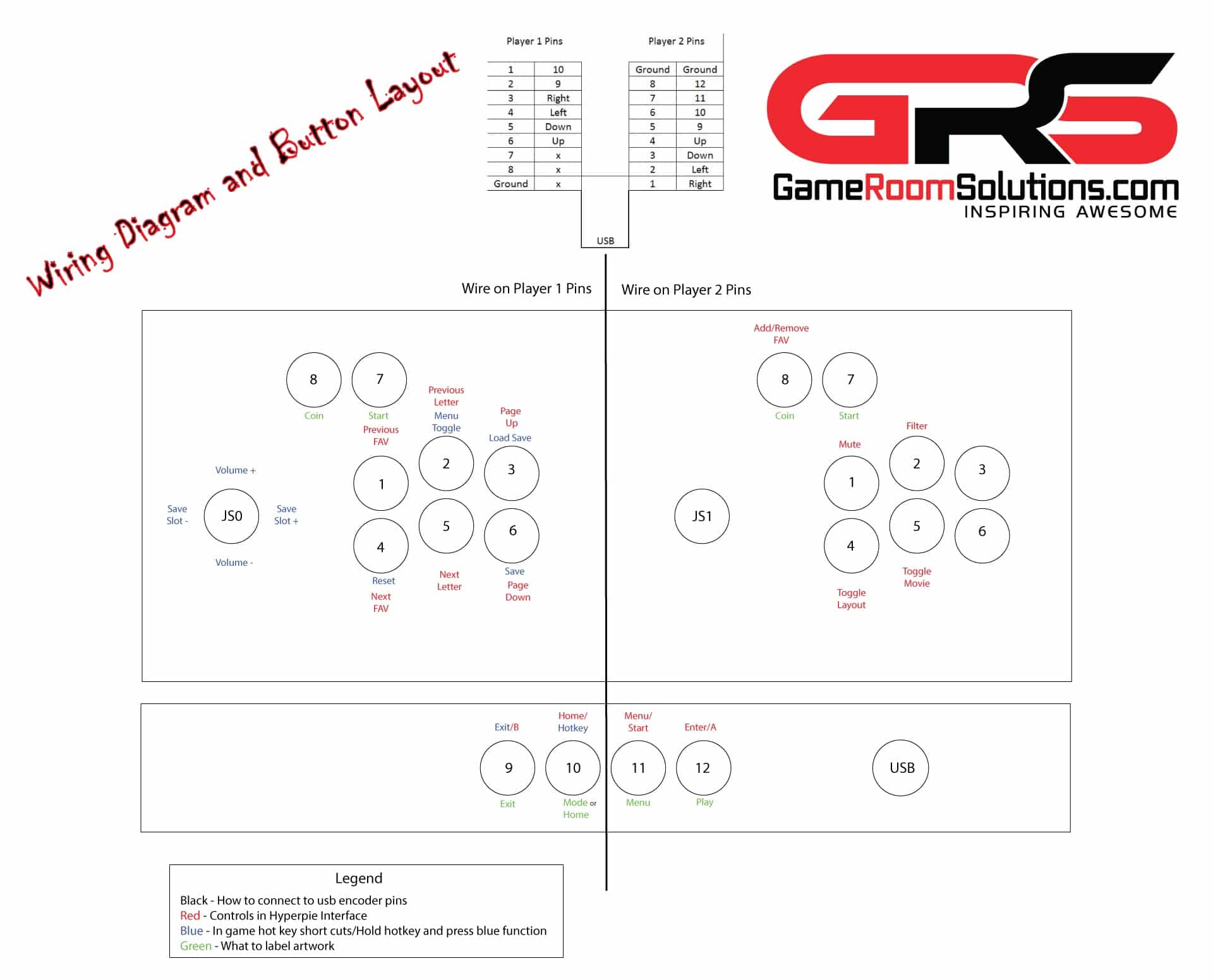
X-Arcade™ BYO Kit Advanced Installation Diagram NOTE: The ground wires are all ground, so you can use any ground with any input as needed. Click to Download NOTE: Mode B is the Save/Load button for programming. Wiring pinout for Mod...
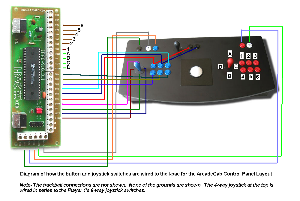
ArcadeCab- MAME Cabinet Plans 2: Wiring the Control Panel
This page covers the arcade controls wiring instruction for The Geek Pub arcade kits. This includes wiring diagrams for the joystick, buttons, LEDs, and zero-delay encoder boards. If you do not have a Geek Pub arcade controls kit, these instructions may still be useful, as most arcade kits are fairly standard wiring.
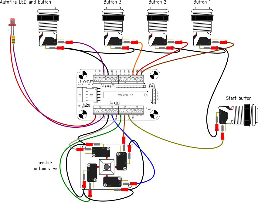
J-ACE Arcade Controls Encoder
This is a shot of of the wiring on the Q*bert boards. Common practice would be to place all the connector with the stickers the same side up. But connector P4 off the Power supply board gets flipped over. If I would have sat down and studied the wiring diagram (like I finally did , determining my problem) I would have saved myself lots of ...
Building An Arcade Controller | Yoseph.Tech
Mar 14, 2018 · Led arcade button wiring diagram. One of the things that made it easy to wire the buttons was the fact that i used the mot ion controller as opposed to a programmable interface board like the ipac. What ever power supply you use the principal is the same. For anything more well have to manually solder them.
Arcade Button Wiring Diagram - Wiring Diagram Networks
There is a color coded wiring diagram on the X-arcade site, also, BTW. The X-Arcade™ was designed to be used with a variety of games and MODE 1 (switch closest to the serial cable, or yellow wire on the switch itself) cannot be programmed. The mouse buttons on the Tankstick/trackball cannot be programmed. it (the purple female plug near the ...

X Arcade Wiring Diagram - Wiring Diagram Schemas
Arcade Warrior (Midi Fighter Pro clone) | Tomash Ghz

Zero Delay Usb Encoder Wiring Diagram ...
How to Upgrade Your Arcade1up to Play 1000's of Games ...

Arcade Wire Diagram - Wiring Diagram Networks

Wiring Dummy Arcade buttons

Mr. Armageddon Builds (Project Log): TableTop Arcade ...
1995
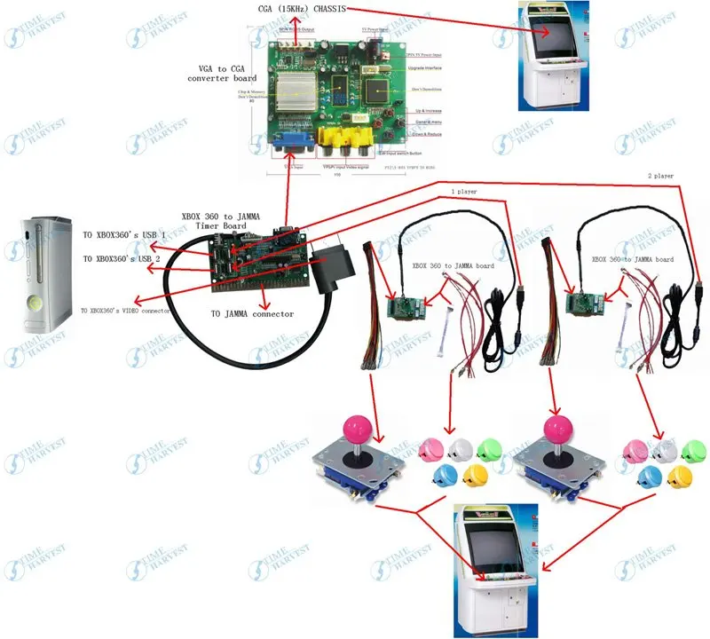
X 360 to arcade machine time board game kit for CGA 15KHz ...
Build Your Own Arcade Controls FAQ - Controls

StealthSwitch3 Arcade Button Installation Info for DIY ...

Arcade Button Wiring Diagram - Wiring Diagram Networks

Arcade Wire Diagram - Wiring Diagram Networks

Xin-Mo Wiring: Arcade Controls on PC or PS3 - YouTube

X Arcade Wiring Diagram - Wiring Diagram Schemas

Mr. Armageddon Builds (Project Log): TableTop Arcade ...

X Arcade Tankstick Wiring Diagram
Arcade Button Wiring Diagram - JEBON-007

Arcade Button Wiring Diagram - Wiring Diagram Networks

Neo Geo MVS: JAMMA: How you connect everything to the board

Rasp Pi as Game Boy » Raspberry Pi Geek

How do I get these Led Arcade buttons to light up ...

Bartop Arcade Machine - Wiring/Joystick/Buttons Setup ...

X Arcade Tankstick Wiring Diagram

Led Arcade Button Wiring Diagram - Wiring Diagram

Mega Joystick Controller To Usb Wiring Diagram | USB ...


Comments
Post a Comment