41 block diagram manipulation
Block Diagrams Block diagrams are usually part of a larger visual programming environment. Other parts of the environment may include numerical algorithms for integration, real-time interfacing, code generation, and hardware interfacing for high-speed applications. Block diagram models consist of two fundamental objects: signal wires and blocks. 160 BLOCK DIAGRAM ALGEBRA AND TRANSFER FUNCTIONS OF SYSTEMS [CHAP. 7 Let the - 1 block be absorbed into the summing point: Step 4c Step 5: By Equation (7.3), the output C, due to input U is C, = [G2/(1 + G1G2)]U. The total output is C=C,+C,= [ ~ 1 +G2G2] [ A] [ A] IGIR + 7.8 REDUCTION OF COMPLICATED BLOCK DIAGRAMS The block diagram of a practical feedback control system is often quite complicated.
Block diagrams are widely used by engineers for controls, signal processing, communications, and mechatronics. Engineers build and use block diagrams to: Block diagram representing flight control system of an aircraft. Engineers rely on the Simulink ® environment to build and simulate block diagrams for multidomain systems efficiently.

Block diagram manipulation
A block diagram is a diagram of a system in which the principal parts or functions are represented by blocks connected by lines that show the relationships of the blocks. They are heavily used in engineering in hardware design, electronic design, software design, and process flow diagrams.. Block diagrams are typically used for higher level, less detailed descriptions that are intended to ... View P02C_Block-Diagram-Reduction1.pdf from EECE EE 132 at Mindanao State University - Iligan Institute of Technology. Block Diagram of Control System Block Diagram Reduction Block Diagram Block diagrams with perspective use 3-D shapes to convey information in a dramatic manner. Create a block diagram. Click the File tab. Click New, under templates, or categories, click General, and then double-click Block Diagram. From the Blocks and Blocks Raised stencils, drag shapes onto the drawing page. To add text to a shape, select the ...
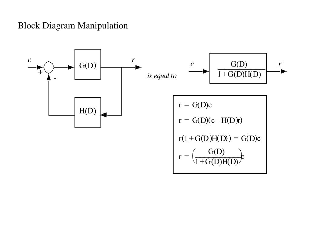
Block diagram manipulation. Block Diagram Manipulation [Section 3.2.] We often represent control systems using block diagrams. A block diagram consists of blocks that represent transfer functions of the different variables of interest. If a block diagram has many blocks, not all of which are in cascade, then it is useful to have rules for Block Diagram Models, Signal Flo w Gra phs and SimpliÞcation Methods Block Diagram Models ¥Visualize input output r elations ¥Useful in design and r ealization of (linear) components ¥Helps understand ßo w of inf ormation betw een internal variables. ¥Are equivalent to a set of linear algebraic equations (of rational functions ). This is a block diagram There are some simple rules of block diagram algebra that make it easy to manipulate systems into a form we want. 1.1 Basic Connections Cascade G 1 (s) G 2 (s) U(s) Y 1 (s) Y 2 (s) Y2psq"G2psqY1psq"G1psqG2psqUpsq Some text/examples in this document c Mathworks. Some materials also obtained from other universities ... Follow these rules for simplifying (reducing) the block diagram, which is having many blocks, summing points and take-off points. Rule 1 − Check for the blocks connected in series and simplify. Rule 2 − Check for the blocks connected in parallel and simplify. Rule 3 − Check for the blocks connected in feedback loop and simplify.
A block diagram is a specialized flowchart used in engineering to visualize a system at a high level. SmartDraw helps you make block diagrams easily with built-in automation and block diagram templates. As you add shapes, they will connect and remain connected even if you need to move or delete items. Introduction to Function Block Programming. One of the most commonly used PLC programming languages is Function Block Diagram, or FBD. Although this language is rarely used for an entire system, it makes a lot of sense in areas where a continuous process flow is taking place or if there's a need for complex instruction sequences that may be laid out much easier in function blocks over ladder ... all steps for block diagram reduction for a complex block diagram. Eliminate loop I & simplify as GGG + B 1G 2H) (sY 4G 2G 1H AB 3G. Visual algebra: use block diagram manipulation instead of algebra. • Block: transfer function of a subsystem. • Line: Laplace transform of a variable. K. Webb MAE 4421 3 Block Diagrams In the introductory section we saw examples of block diagrams to represent systems, e.g.: Block diagrams consist of Blocks-these represent subsystems - typically modeled by, and labeled with, a transfer function Signals- inputs and outputs of blocks -signal direction indicated by
Block Diagram Reduction & Manipulation Dr. Haitham El-Hussieny Adjunct Lecturer Space and Communication Engineering Zewail City of Science and Technology Fall 2016 Dr. Haitham El-Hussieny SPC318: System Modeling and Linear Systems1 / 40. Lecture Outline: 1 Block Diagram Representation. A block diagram majorly comprises rectangle shapes known as blocks and the straight lines with arrows at the end. While the blocks represent the key elements of the entire process, the arrowed lines show the relationship between the two objects and the direction the data, information, processing, signals, or the electric current flows in. 160 BLOCK DIAGRAM ALGEBRA AND TRANSFER FUNCTIONS OF SYSTEMS [CHAP. 7 Let the - 1 block be absorbed into the summing point: Step 4c Step 5: By Equation (7.3), the output C, due to input U is C, = [G2/(1 + G1G2)]U. The total output is C=C,+C,= [ ~ 1 +G2G2] [ A] [ A] IGIR + 7.8 REDUCTION OF COMPLICATED BLOCK DIAGRAMS The block diagram of a practical feedback control system is often quite complicated. 422 Block diagram manipulation. There are occasions when there is interaction between the control loops and, for the purpose of analysis, it becomes necessary to re-arrange the block diagram configuration. This can be undertaken using Block Diagram Transformation Theorems. Table 4.1 Block Diagram Transformation Theorems.
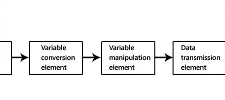
Generalized Measurement System Block Diagram Elements Stages Example Engineering Tribe
A block diagram of the closed loop control system is shown in Figure. The operations in the closed loop system are performed by output measuring devices, comparators, amplifiers, controllers and system plant. The measuring devices produce signal proportional to the actual system output.

Block Diagram Analysis Process Control Modeling Design And Simulation Book
Block diagram . A control system may consist of a number of components. A block diagram of a system is a pictorial representation of the functions performed by each component and of the flow of signals. The elements of a block diagram are block, branch point and summing point. Block
2
Block Diagram Reduction Rules - Control System. We have discussed in our previous article that for the easiness of analysis of a control system, we use block diagram representation of the control system. Basically we know that a complex system is difficult to analyze as various factors are associated with it.

Getting More From Simulation Part 3 Component Orientated Modelling Versus Block Diagram Modelling Claytex
11. 1. Hello I hope someone can help me, as i am kinda stuck for the moment. As you can see, the assignment states that I need to find the poles from the closed loop transfer function. I plan on doing so, by using block diagram reduction method. This is as fare as i've come, and can't come further, even though I am pretty sure that it is possible.

Block Diagram Models Block Diagram Manipulation Diagram Models Signal Flo W Gra Phs And Block Diagram Reduction Control 3b Pdf Author Lavi Shpigelman Pdf Document
In control engineering, the block diagram is a primary tool that together with transfer functions can be used to describe cause-and-effect relationships throughout a dynamic system. The manipulation of block diagrams adheres to a mathematical system of rules often known as block diagram algebra.
Block Diagram Manipulation Physics Forums
Block Diagram manipulation Thread starter Hraabo; Start date Apr 23, 2019; Tags engeneering regulation stuck student Apr 23, 2019 #1 Hraabo. 11 1. Hello I hope someone can help me, as i am kinda stuck for the moment. As you can see, the assignment states that I need to find the poles from the closed loop transfer function.

Tikz Examples Tag Block Diagrams
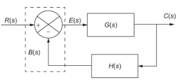
Block Diagram of Closed Loop Control System. In a closed-loop control system, a fraction of output is fed-back and added to the system's input. If H (s) is the transfer function of the feedback path, then the transfer function of the feedback signal will be B (s) = C (s)H (s). At the summing point, the input signal R (s) will be added to B (s ...
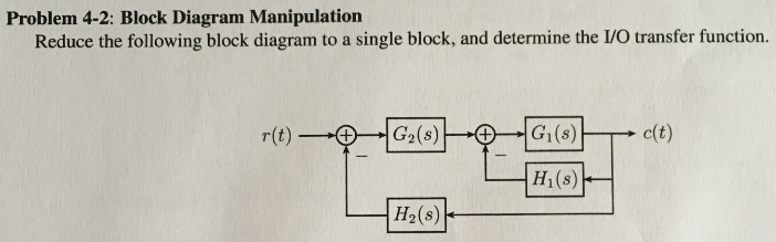
Solved Problem 4 2 Block Diagram Manipulation Reduce The Chegg Com
K. Webb ESE 499 3 Block Diagrams In the introductory section we saw examples of block diagrams to represent systems, e.g.: Block diagrams consist of Blocks - these represent subsystems - typically modeled by, and labeled with, a transfer function Signals - inputs and outputs of blocks - signal direction indicated by arrows - could be voltage, velocity, force, etc.

Easy To Use Sysml Modeling Software
Basic Elements of Block Diagram. The basic elements of a block diagram are a block, the summing point and the take-off point. Let us consider the block diagram of a closed loop control system as shown in the following figure to identify these elements. The above block diagram consists of two blocks having transfer functions G(s) and H(s).
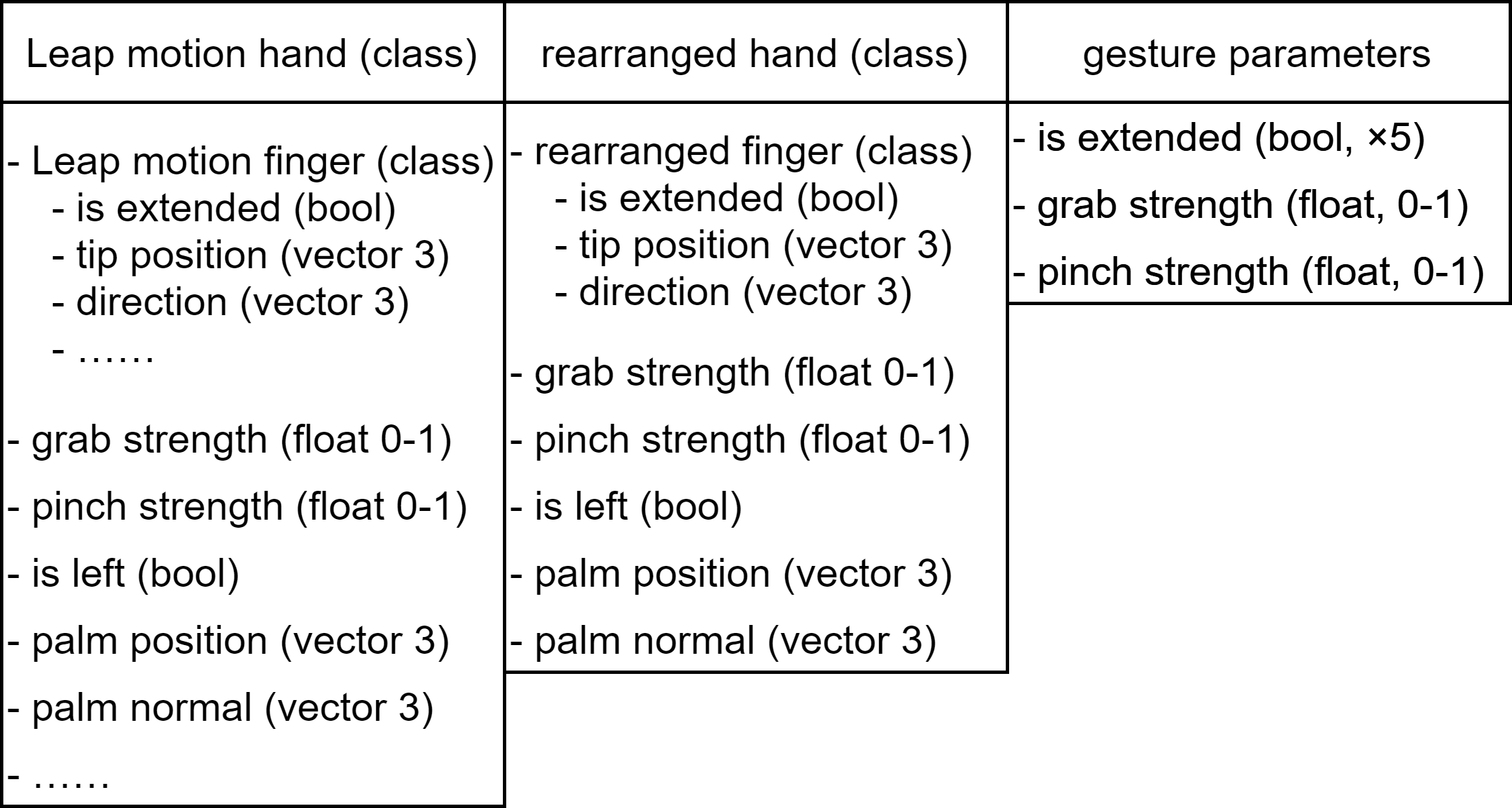
Block Diagram Of Gesture Manipulation Lemur
Block Diagram Manipulation. RI(s) Title: Microsoft PowerPoint - Tutorials.ppt Author: Leo Created Date: 9/10/2008 11:16:42 AM ...
Ppt Chapter Feedback Powerpoint Presentation Free Download Id 511132
Uses block diagram algebra to find the transfer function relating an input to an output. Made by faculty at Lafayette College and produced by the University ...
Block Diagram Reduction Technique Electronics Club
The block diagram includes reference input, control elements, plant, and feedback elements. In between, there is an addition of specific variables and signals. Such visual representation of block diagrams is available on online block diagram makers like EdrawMax.
Read Online Block Diagram Models Block Diagram Manipulation Rules Free E Book
Block diagrams with perspective use 3-D shapes to convey information in a dramatic manner. Create a block diagram. Click the File tab. Click New, under templates, or categories, click General, and then double-click Block Diagram. From the Blocks and Blocks Raised stencils, drag shapes onto the drawing page. To add text to a shape, select the ...

Diagram Manipulation And Reduction Control Systems Pdf Control Theory Control System
View P02C_Block-Diagram-Reduction1.pdf from EECE EE 132 at Mindanao State University - Iligan Institute of Technology. Block Diagram of Control System Block Diagram Reduction Block Diagram

Closed Loop System And Closed Loop Control Systems
A block diagram is a diagram of a system in which the principal parts or functions are represented by blocks connected by lines that show the relationships of the blocks. They are heavily used in engineering in hardware design, electronic design, software design, and process flow diagrams.. Block diagrams are typically used for higher level, less detailed descriptions that are intended to ...
Wescott Design Services Using Block Diagrams
Loop Reversal Rule In Block Diagram And Signal Flow Graph Manipulation Semantic Scholar
2
2
1
2

Block Diagram Matlab Simulink
2
1
Block Diagram Manipulation Physics Forums
2

Control Systems Engineering Lecture 5 Block Diagrams Youtube

Easy To Use Sysml Modeling Software
Control Systems Block Diagram Reduction
Loop Reversal Rule In Block Diagram And Signal Flow Graph Manipulation Semantic Scholar

Control Tutorials For Matlab And Simulink Introduction Simulink Modeling
Block Diagram Archives Polytechnic Hub
Block Diagram Manipulation Physics Forums

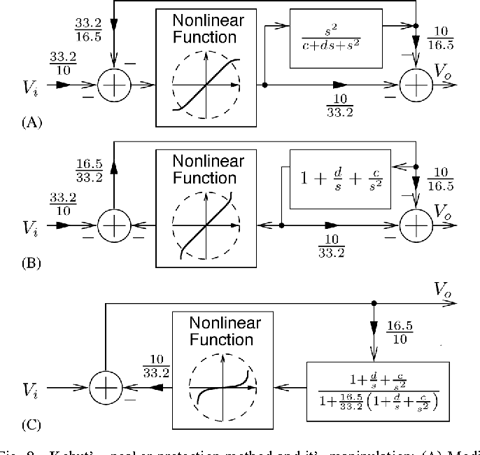
Block Diagram Manipulation Steps To A 2 Parameter Form Of Figure 5 B Download Scientific Diagram

Block Diagram Manipulation

Se 302 Linear Systems L6 Ppt Se 302 Linear Systems Block Diagram And Sfg Manipulation Dr Fouad M Al Sunni What Is The Transfer Function Tf Is Defined Course Hero
Wescott Design Services Using Block Diagrams
Simplification

Manipulation Of The Operating Point Model Block Diagram Yields Very Download Scientific Diagram
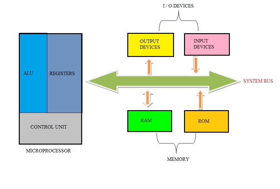
Difference Between Microprocessor And Microcontroller

The Block Diagram Of The Proposed Manipulation Framework Download Scientific Diagram


Comments
Post a Comment