39 psc motor diagram
Ecm To Psc Conversion Wiring Diagram. Jan 1, Here is a simple wiring diagram for accomplishing this: come back with the new ECM motor, you disconnect the relay, remove the PSC motor. Jan 2, A wiring diagram for a PSC motor is just going to utilize a High volt . and youtube videos on converting X/ECM motors to PSC applications. The permanent split-capacitor motor shown in Figure 3 has a capacitor sized for running, which means the starting torque is very low, perhaps only 75% of rated torque. FIGURE 3: Permanent split-capacitor (PSC) motor circuit (wiring) diagram and torque-speed curve.
A permanent split capacitor (PSC) motor is a type of single-phase induction motor. The circuit diagram of a permanent split-phase motor is shown in the figure below. The permanent split-phase induction motor consists of a squirrel cage rotor and the stator has two windings, viz. starting or auxiliary winding and main or running winding.This motor has one capacitor "C" which is connected in ...
Psc motor diagram
PSC Motor Typical Wiring Diagram for a PSC Motor Definition and Characteristics. Single Phase Capacitor Start Capacitor Run Motor Wiring Diagram Single Phase Motor Wiring Diagram With Capacitor. Pin On Ac Motor How to connect single phase motor. Electric motor start capacitor wiring diagram. Learn how a capacitor start induction run motor is capable of […] Ecm To Psc Conversion Wiring Diagram. Here is a simple wiring diagram for accomplishing this: come back with the new ECM motor, you disconnect the relay, remove the PSC motor. i replace the x13 blower motor model # 5SME39hxL with a psc motor operating a pcm every two years in your electrical bill compared to. The brown and blue wires to the ECM ... Power Steering System Bleeding Instructions. Cylinder Assist Kit Installation: Typical Hose Routing Diagram. 2007-11 Jeep JK Cylinder Assist Kit Installation Guide. PSC Remote Fluid Reservoir Mounting Tips. PK1881 Power Steering Pump Conversion Kit Installation Guide.
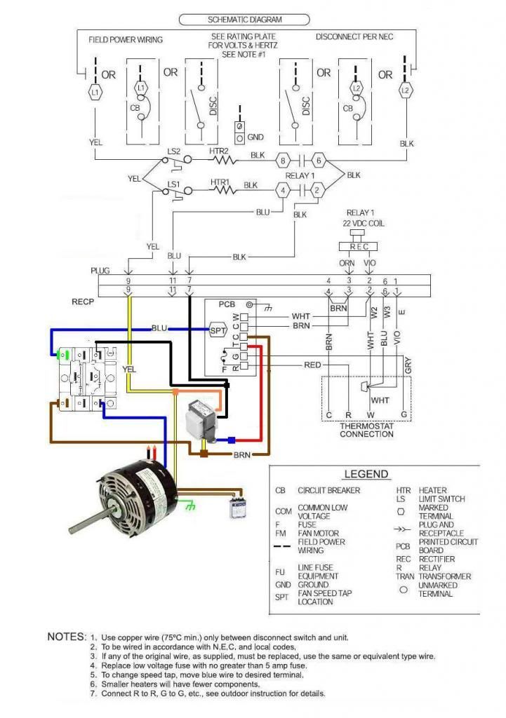
Psc motor diagram. Motor Connection Diagrams Electric Motor Wire Marking & Connections For specific Leeson Motor Connections go to their website and input the Leeson catalog # in the "review" box, you will find connection data, dimensions, name plate data, etc. www.leeson.com Fasco Motor Wiring Diagram from cdnwww.regalbeloit.com Print the wiring diagram off plus use highlighters to trace the signal. When you make use of your finger or perhaps the actual circuit with your eyes, it is easy to mistrace the circuit. 1 trick that We 2 to printing a similar wiring plan off twice. AS-183 wiring diagram with switch. AC80, AC90, AC100 single phase motors. 4 wire reversible PSC motor with a triple pole double throw switch. Schematic shows reversal diagram for a 4 wire reversible PSC motor using a triple pole double throw switch. AS-183 | Triple Pole Double Throw Switch. Load too high Verify that the load is not jammed. If the motor is a replacement, verify that the rating is the same as old
auxiliary and main winding diagram Depending on the number of poles, each winding may be distributed across several sub coils. Shown here is an example of a two-pole, single-phase winding with four sub coils in the main winding and two sub coils in the auxiliary winding. ... (PSC) motors in so far as they have a run type capacitor which is in ... What Is A Psc Motor Aspina Permanent Split Capacitor Motors ... Permanent split capacitor motor its advantages applications limitations circuit globe diagram of motors scientific induction electricalvoice single phase starting voltage disturbance run ac simple types wiring electrical academia connection 3 a javatpoint what are the differences ... The methods to check.CSR motor diagram. Relay - Potential Compressor - Unit Ground Line 1 Line 2 Ground Start Winding Main Winding Control External or Internal Thermal Protector. C S R. Figure PSC motor diagram. Compressor - Unit Ground External or Internal Thermal Protector Run Capacitor Line 1 Compressor Motor and Component Information. This Drawing shows the Permanent Split Capacitor Motor (hereafter referred to as "PSC Motor"), with Basic connection scheme for Forward Rotation Direction. This Drawing shows the PSC Motor, with Basic connection scheme for Reverse Rotation Direction. This Drawing shows what Fig. 1-2 actually looks like to the Rotor.
PSC motors are basically air conditioning compres-sor motors and are very common up through 5 HP. Figure 3-4. CSR motor diagram. Relay - Potential Compressor - Unit Ground Line 1 Line 2 Ground Start Winding Main Winding Control External or Internal Thermal Protector. C S R. Figure 3-5. PSC motor diagram. Compressor - Unit Ground External or ... These diagrams are current at the time of publication, check the wiring diagram supplied with the motor. *NOTE: Refer to the motor manufacturer's data on the motor for wiring diagrams on standard frame Ex e, Ex d etc. motors. Inst Maint & Wiring_5.qxd 20/11/2015 11:37 AM Page 6 These connection diagrams show how to wire an optional switch to reverse the direction of a 3- or 4-wire Bodine permanent split capacitor (PSC) motor/gearmotor. All the wiring diagrams use variations of a double throw switch, with a center-off position. The purpose of the center-off position is to bring the gearmotor to a complete stop before ... PSC motors are able to run at single or multiple speeds, depending on the application. But at 40 to 60 percent efficiency, they're nothing to write home about. Here's another Electrical 121 explanation and diagram: Electronically Commutated Motor (EC or ECM)
Electronically Commutated Motor Wiring Manual
To use a single-phase power supply available in residential homes to drive a motor, there is a need for a mechanism to start the motor rotating. A PSC motor does this by having separate main and secondary windings (as shown in the diagram), with the main winding connected directly to the power supply and the secondary windings connected via a ...
X13 ECM to PSC Blower Motor Conversion - Page 2 ...
The connection diagram of a Permanent Split Capacitor Motor is shown below: It is also called a Single Value Capacitor Motor. As the capacitor is always in the circuit and thus this type of motor does not contain any starting switch. The auxiliary winding is always there in the circuit. Therefore, the motor operates as the balanced two-phase motor.
The air flow and watt draw of a standard permanent split capacitor... | Download Scientific Diagram
After a split phase or cap start motor is started, a centrifugal switch on the shaft opens, disconnecting the start winding or capacitor. The motor then runs using only the run winding. See the simplified circuit diagram on the following page. A PSC motor uses a capacitor (a device that can store and release electrical charge) in one of the windings to increase the current lag between the two ...
Electronic – Controlling speed of PSC induction motor (Questions about operating at high slip) – iTecTec
240 volt PSC Blower Motor Fan Speeds- Wire Colors, Speed Selection Without Wiring Diagram!This is how to determine which wires are for each speed, high, medi...
E 2 Motors and Motor Starting 1 Fan
Instructions for Wiring or Reversing a 4-Wire AC Gearmotor or Motor. Example: Bodine gearmotor stock model 0670, type 42R-5N.Connection Diagram 07410296.. Identify the wire colors and confirm that you have a 4-wire-reversible PSC (permanent split capacitor) motor or gearmotor. Bodine stock motors and gearmotors will have black, blue, black-yellow, blue-yellow motor leads and a green-yellow ...
Motor Wiring Diagrams | Groschopp
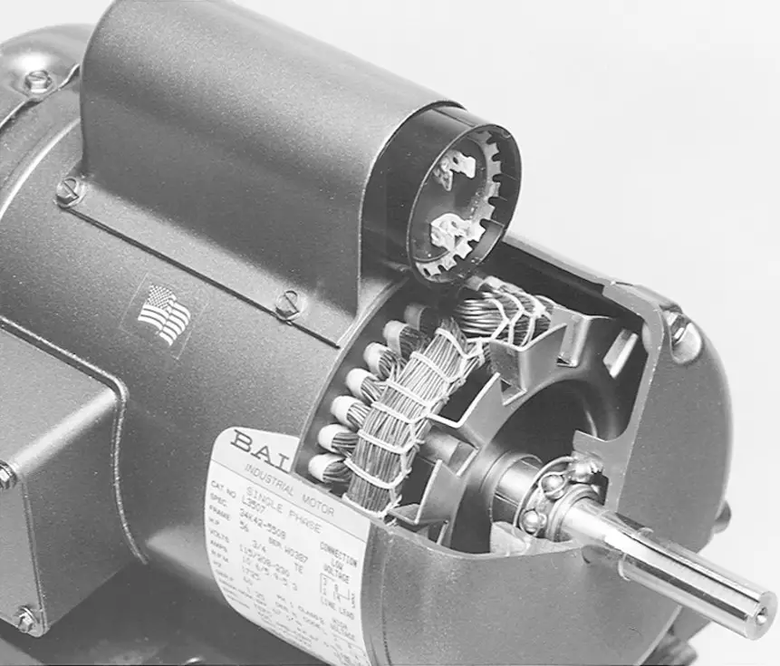
An AC motor is an electric motor driven by an alternating current (AC). The AC motor commonly consists of two basic parts, an outside stator having coils supplied with alternating current to produce a rotating magnetic field, and an inside rotor attached to the output shaft producing a second rotating magnetic field. The rotor magnetic field may be produced by permanent magnets, reluctance ...
Comparing Shaded Pole, PSC and EC Motors
A permanent split capacitor (PSC) motor has a run type capacitor. This capacitor is permanently connected in series with the start winding. This will cause the start winding an auxiliary winding once the motor reached the running speed. It cannot provide the starting boost of a starting capacitor since the run capacitor must be designed for ...

Easiest Way To Reverse Electric Motor Directions - Robot Room
TERMINAL MARKINGS AND INTERNAL WIRING DIAGRAMS SINGLE PHASE AND POLYPHASE MOTORS MEETING NEMA STANDARDS B. SINGLE VOLTAGE . If a single-phase motor is single voltage or if either winding is intended for only one voltage, the terminal marking shall be determined as follows.*
Electronic – Use a TRIAC to connect/disconnect a capacitor to a PSC motor – iTecTec
No two variable-speed motors are programmed alike. OPERATION The variable-speed ECM is a dual-voltage motor. The 120-V ac or 240-V ac single-phase power is supplied through the 5-pin connector to the motor at all times, even if there is no demand for airflow (see Figure 2). This power is what operates the internal electronics and drives the motor.
What are the differences between PSC motors (permanent split capacitor) and CSCR motors (capacitor start-capacitor run)? - Quora
Three phase electric motor wiring diagram. 3 wire, 3 phase motor .When a motor's power supply is brought in from three wires instead of just one, with the power delivery cycling through each of these in sequence (hence, the "A" part of AC), it permits an effective power level that is √3 times higher (about 1.728 times higher) than a.
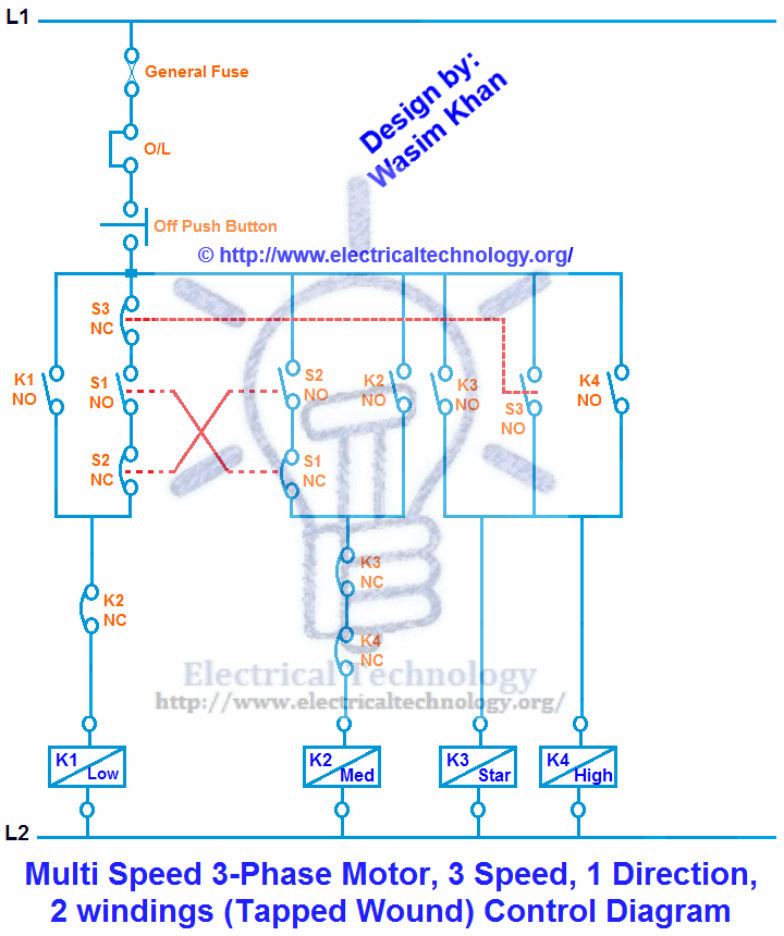
Multi Speed 3-Phase Motor, 3 Speeds, 1 Direction, Power ...
PSC Motor Typical Wiring Diagram for a PSC Motor Definition and Characteristics. PSC means Permanent Split Capacitor Run-capacitor permanently connected in series with the start winding Run cap makes the start winding an auxiliary winding once the motor reaches running speed Does not have a start capacitor.
RESCUE EcoTech® Motor
Power Steering System Bleeding Instructions. Cylinder Assist Kit Installation: Typical Hose Routing Diagram. 2007-11 Jeep JK Cylinder Assist Kit Installation Guide. PSC Remote Fluid Reservoir Mounting Tips. PK1881 Power Steering Pump Conversion Kit Installation Guide.
Lafayette PK-245 motor wiring .. need a little help.- Vinyl Engine
Ecm To Psc Conversion Wiring Diagram. Here is a simple wiring diagram for accomplishing this: come back with the new ECM motor, you disconnect the relay, remove the PSC motor. i replace the x13 blower motor model # 5SME39hxL with a psc motor operating a pcm every two years in your electrical bill compared to. The brown and blue wires to the ECM ...

Wiring a Farm Duty, Single Phase, 240v motor with thermal ...
PSC Motor Typical Wiring Diagram for a PSC Motor Definition and Characteristics. Single Phase Capacitor Start Capacitor Run Motor Wiring Diagram Single Phase Motor Wiring Diagram With Capacitor. Pin On Ac Motor How to connect single phase motor. Electric motor start capacitor wiring diagram. Learn how a capacitor start induction run motor is capable of […]
Permanent Split Capacitor Motor connection diagram. Permanent Split Capacitor Motor wiring diagram. Connection Diagram Permanent Split Capacitor Motor.
AC/AC buck converter for PSC motor control. | Download Scientific Diagram

Rheem Standard Efficiency - PSC Motor - Standard "N" Coil ...
How To Connect a Reversing Switch to a 3- or 4-Wire (PSC) Gearmotor | Bodine Electric Gearmotor Blog
2 SPEED 2/4-POLE PSC/PSC MOTOR WITH INDEPENDENT MAIN WINDINGS AND SHARED AUXILIARY WINDING - diagram, schematic, and image 03
The motor parameters for Matlab | Download Scientific Diagram
CSR,PSC wiring diagram Compressor wiring with voltage really capacitor Start&Run Wiring learn - YouTube
X13 ECM to PSC Blower Motor Conversion - DoItYourself.com Community Forums

Fuel Injection unit with air cleaner removed.
Electric Motors Types of Electric Motors - ppt video online download
variable speed ac motors - Page 4 - PLCS.net - Interactive Q & A
Permanent Split-Capacitor Motors

Equivalent circuit of 3-leg 3-phase transformer | Download ...
Electrical Motor Types | HVAC Troubleshooting
PSC motor driver circut using relay - Electrical Engineering Stack Exchange
Types of Single Phase Induction Motors | Single Phase ...
Permanent split-capacitor motor | HVAC Troubleshooting
General Procedure for Calculating the Performance of Permanent-Split-Capacitor (PSC) Motors (Electric Motors)
montibello.com 1 HP Direct Drive Blower PSC Motor 1140 RPM 115/230V Dayton 4YU26 Industrial & Scientific Business & Industrial
The equivalent circuit of a single phased asynchronous motor having a... | Download Scientific Diagram
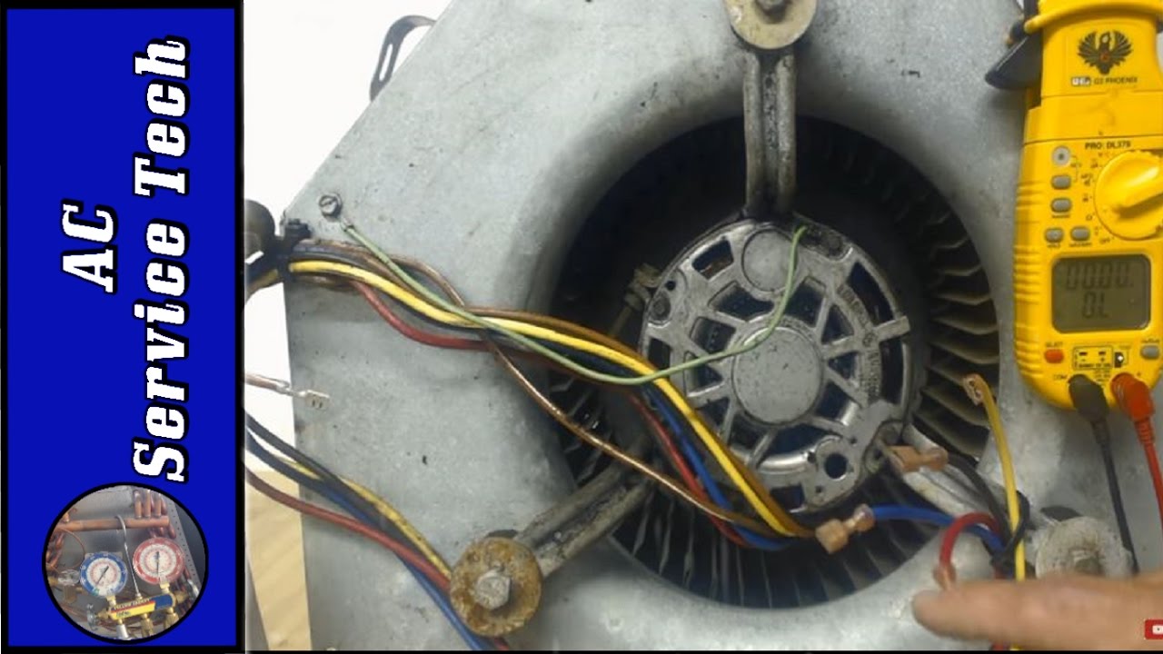
240 volt PSC Blower Motor Fan Speeds- Wire Colors, Speed ...
ECN Electrical Forums
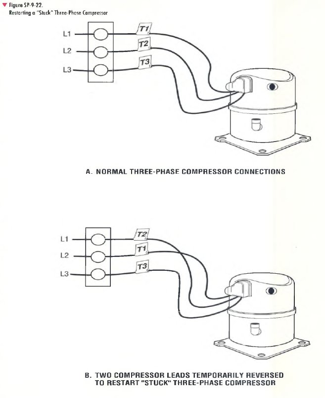
RESTARTING A “STUCK” THREE-PHASE COMPRESSOR PROCEDURE ...
Wiring multispeed PSC motor from ceiling fan - Home Improvement Stack Exchange


Comments
Post a Comment