39 cable headend diagram
The Crypton company will help you organize cable and IPTV broadcasting. Headend of hybrid TV. Digital head stations of CATV and interactive television. Block diagram. A cable television headend is a master facility for receiving television signals for processing and distribution over a cable television system. A headend facility may be staffed or unstaffed and is typically surrounded by some type of security fencing. The building is typically sturdy and purpose-built to provide security, cooling, and easy access for the electronic equipment used to receive ...
[Cable television headend. Wikipedia] This regional cable head-end diagram example was created using the ConceptDraw PRO diagramming and vector drawing software extended with the Computer and Networks solution from the Computer and Networks area of ConceptDraw Solution Park.

Cable headend diagram
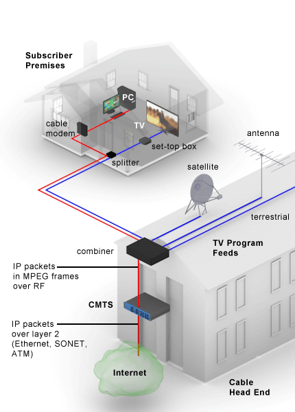
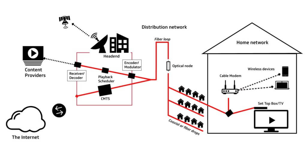
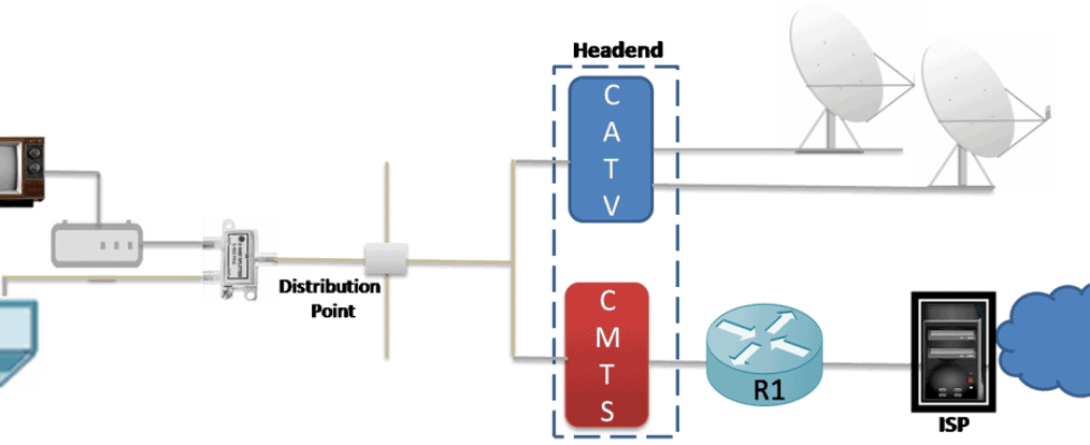
In this diagram, there is a Cable Modem Termination System (CMTS) that consists of these ... document; refer to Connecting the Cisco uBR7200 Series Router to the Cable Headend for proper RF setup and measurements. Assumptions The upconverter is already installed and configured properly. Refer to the vendor's Signal output from headend and details of distribution system: To determine the signal level required from the Headend system, a basic description of the distribution system is needed - info to include: layout of complex, number of outlets and representative cable run lengths. Click for Headend Diagram - Fig 1. 36 Channel MATV Headend System - Cable - Leased line - Metro-optical 1.0 Networking Fundamentals Compare and contrast the Open Systems Interconnection (OSI) model layers and encapsulation concepts. Explain the characteristics of network topologies and network types. 1.1 1.2 CompTIA Network+ Certification Exam Objectives 3.0 (Exam Number: N10-008)
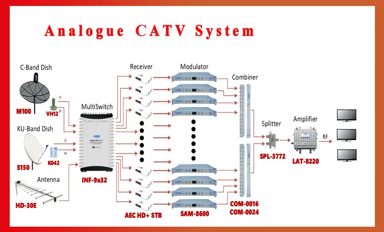
Cable headend diagram. A Digital Headend system is a new revolution in cable TV industry. Digital Headend changed the whole phenomenon of cable TV industry by increasing the number of services. A large number of services can be run on a digital headend. Also digital headend system reduces the bandwidth and provide us better pitcher quality. Diagram Details : - Digital Headend Diagram Download - High Quality Description : A Digital Headend system is a new revolution in cable TV industry. Digital Headend changed the whole phenomenon of cable TV industry by increasing the number of services. Format : .jpg File Dimensions : 7000 Px Width * 2430 Px Height DPI : 300 Size : 5.70 MB Uses : Free For Commercial Use !!! Cable television is a system of delivering television programming to consumers via radio frequency (RF) signals transmitted through coaxial cables, or in more recent systems, light pulses through fibre-optic cables.This contrasts with broadcast television (also known as terrestrial television), in which the television signal is transmitted over-the-air by radio waves and received by a ... The complete cable TV system is depicted in the figure above. CATV companies offer the cable TV service. Let us understand the entire process: • Cable TV companies collect broadcasted TV signals using very high gain TV antennas. This place is also referred as headend. Later these received TV signal programming is re-distributed.
26.4.2018 · Free BICSI RCDD Exam Practice Test Questions Covering Latest Pool. Study with Exam-Labs RCDD RCDD Exam Practice Test Questions and Answers Online. This diagram shows that the cable television operator's head end system contains both analog and digital television channel transmitters that are connected to customers through the distribution lines. The distribution lines (fiber and/or coaxial cable) carry over 100 television RF channels. Headend solutions are available with a variety of splitter, coarse wavelength division multiplexing (CWDM), ... indoor splice enclosure that simplifies cable termination, splicing, and fiber storage. The OSE accepts both indoor and outdoor cables through ... Please refer to the numbered diagram on previous page. Analog Cable TV System Part-1 CATV Headend system installation | CATV Modulators Installation Urdu / Hindi in this video i want to show you how to install C...
The vector stencils library "Cable TV" contains 64 symbols of cable TV network equipment. Use these shapes for drawing CATV system design floor plans, network topology diagrams, wiring diagrams and cabling layout schemes in the ConceptDraw PRO diagramming and vector drawing software. The vector stencils library "Cable TV" is included in the Electric and Telecom Plans solution from the Building ... Below is a wiring diagram that compares the individual pin-outs for Standard/High Speed HDMI Cables with an Ethernet Channel, and without an Ethernet Channel: Something else you might be interested in: On the Multicom Online Store you will find the best HDMI Cable on the market: HDMI 2.0, 4K Certified with Internet, 6 feet (1.8m) – for the unbelievable price of $1.15 and FREE Shipping! CMTS is Headend Equipment which is located at Digital Headend. CMTS is used to provide the data and voice services to the cable tv subscribers. RF output from CMTS is mixed with the RF of cable tv services. A cable modem is installed at the subscriber end to provide these service to the subscriber. These equipments are called digital headend equipment.While equipment required for cable tv are from dish antenna to ground.In cable tv equipment, headend equipment and field equipment both are combined. In this article we let you know that how step by step signal goes threw these cable tv equipment to the customer end.
Cable Tv Basics Tutorial Cable Tv System Modules
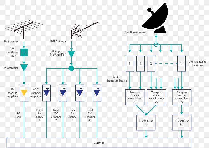
A typical system like the one shown in the diagram includes power splitters and jumper cables feeding all the panels. Digital Headend The Headend consists of modules that encode and combine local television signals or digital signals from satellite receivers.

Mfh 2 Concept2 Multicom
IPTV headend provides three services like cable tv,VOIP and Internet service. To understand the IPTV headend we have block diagram for IPTV headend Equipment below, As mentioned above in the figure we receive the signal from satellite via dishes.This signal of dishes goes into decoders as RF input.Then decoders decode the signal and output of ...
Smatv Cable Television Headend Satellite Dish Asiasat Television Receive Only Png 800x581px Smatv Aerials Area Asiasat
The vector stencils library "Cable TV" contains 64 symbols of cable TV network equipment. Use these shapes for drawing CATV system design floor plans, network topology diagrams, wiring diagrams and cabling layout schemes in the ConceptDraw PRO diagramming and vector drawing software. The vector stencils library "Cable TV" is included in the Electric and Telecom Plans solution from the Building ...
Cable Head End Article About Cable Head End By The Free Dictionary
the headend for delivery over HFC cable networks using cable data modems. INTRODUCTION Until a few years ago, the broadcast industry (cable, off-air, and satellite) was limited to the broadcast of television programming. Computers were used for scientific and industrial purposes, and the telecommunication

Communication Networks Cable Wikibooks Open Books For An Open World
DAS Headend 3. Remote Radio Units Converts RF signal to digital signal for distribution. Coaxial cable and passive components connect to indoor antennas. Receives, amplifies, conditions and combines signal sources. Fiber optic or Ethernet cable connects the …
Up To 74 Fdi Allowed For Headend In The Sky Government Public Sector India
I need to find a diagram or the main components within a headend, and some information on how the signal is being received, processed, combined and transmitted. I have a very high level view on how it works, i.e. receive signal, demodulate, descramble, remultiplex etc but I need it in more detail especially about the processing part of the ...

Innovative Mixed Signal Chipset Targets Hybrid Fiber Coaxial Cable Modems Analog Devices
Cable Tv Headend Diagram Image Master Cable and Service Sumber : masterlawservice.com Cable TV Vector stencils library Draw The Block Digram The vector stencils library Cable TV contains 64 symbols of cable TV network equipment Use these shapes for drawing CATV system design floor plans network topology diagrams wiring diagrams and cabling ...

The Hybrid Fiber Coaxial Hfc Network Telecommunications
"A cable television headend is a master facility for receiving television signals for processing and distribution over a CATV system. The headend facility is normally unstaffed and surrounded by some type of security fencing and is typically a building or large shed housing electronic equipment used to receive and re-transmit video over the local cable infrastructure. One can also find head ...
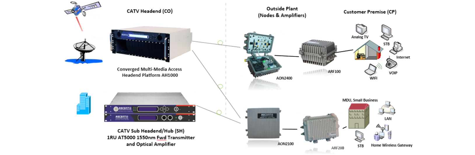
Ascent Communication Technology
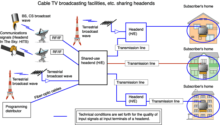
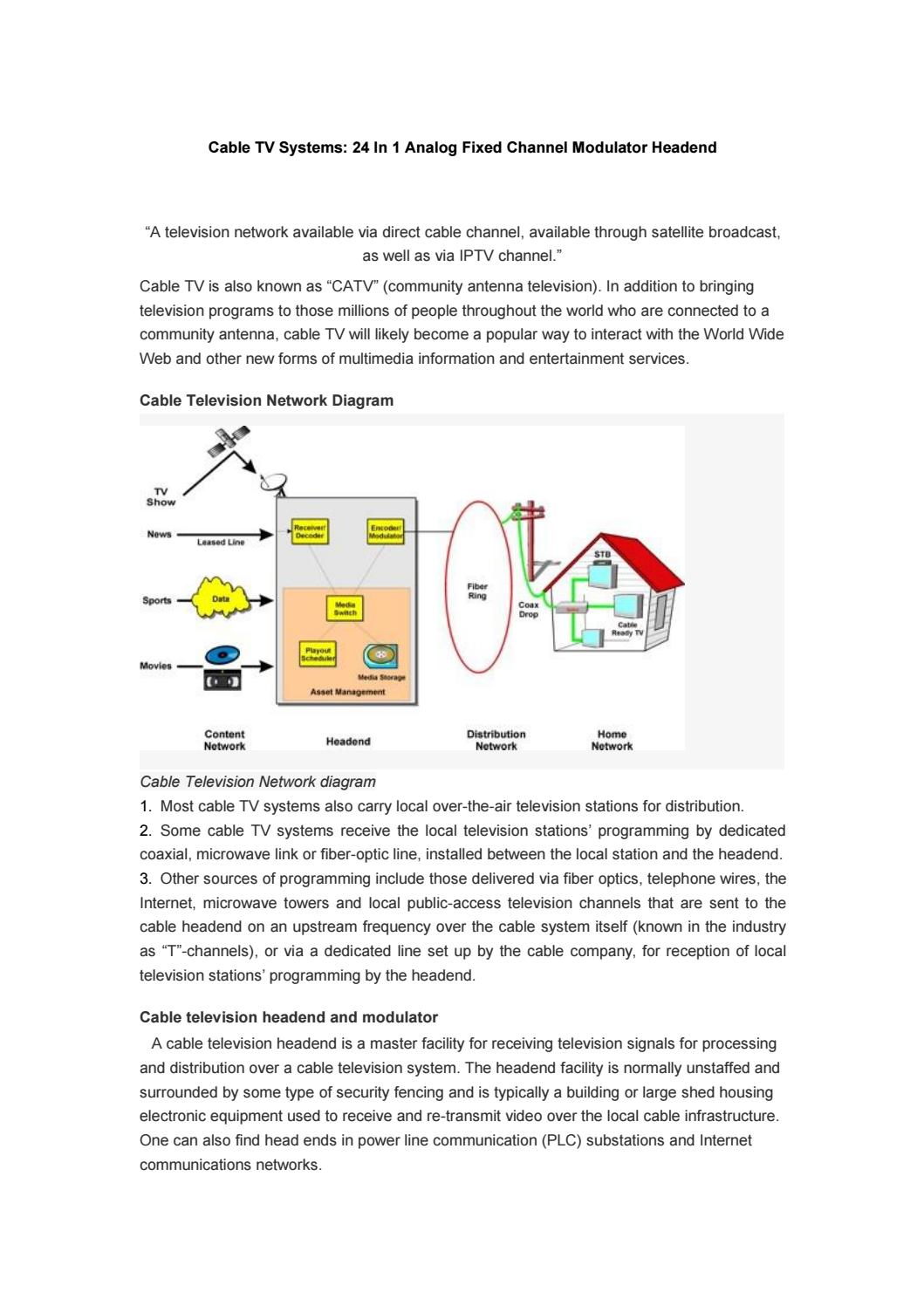
Cable Television Network Diagram. Cable Television Network diagram. Most cable TV systems also carry local over-the-air television stations for distribution. Some cable TV systems receive the local television stations' programming by dedicated coaxial, microwave link or fiber-optic line, installed between the local station and the headend.

This Digital Headend System Block Diagram Stock Illustration 1266797533
DOCSIS Cable Headend Architecture Diagram. For reference purposes, here is a very high-level drawing of the major elements of a Motorola cable headend and how they typically connect. This drawing covers legacy SCTE 55-1 and 55-2 topology, which addresses out-of-band signaling to legacy set-top boxes.
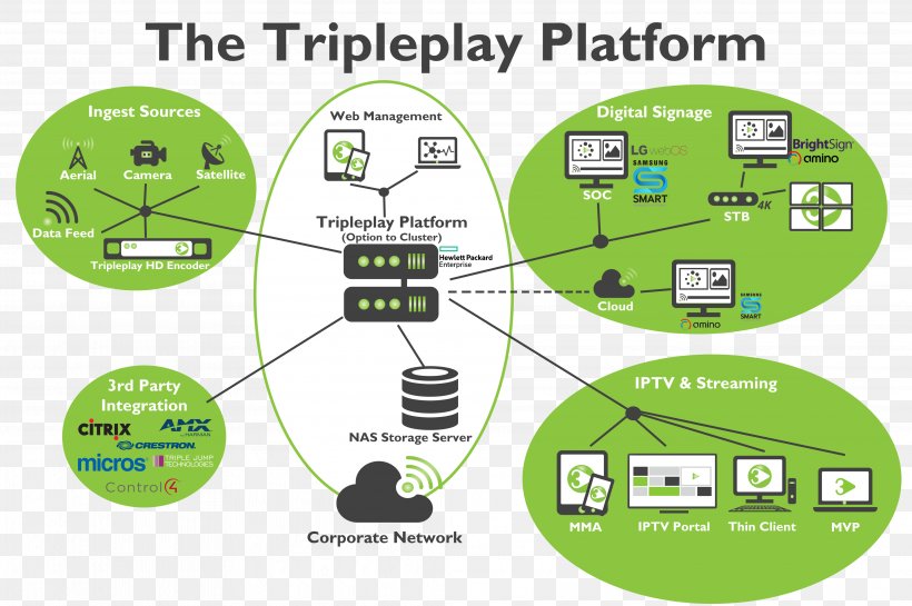
Diagram Technology Triple Play Iptv Video On Demand Png 4134x2750px Diagram Area Brand Business Cable Television
Coaxial cable is commonly used by cable operators, telephone companies, and internet providers around the world to convey data, video, and voice communications to customers. It has also been used extensively within homes. It has been around for a long time as a technology (since the early 20th century) and has many singular advantages for reliable, accurate transmission.

Cable Tv Hybrid Fiber Coax Hfc Architectures Download Scientific Diagram
Cable Headend Optics ... Wiring Diagram. Click on image to enlarge. Close Modal. Electrical Specifications. dc Resistance, maximum 0.3 ohm: Safety Voltage Rating 300 V: Material Specifications. Contact Plating Material Precious ...
Scirp Org
Regional cable head-end diagram. "A cable television headend is a master facility for receiving television signals for processing and distribution over a CATV system. The headend facility is normally unstaffed and surrounded by some type of security fencing and is typically a building or large shed housing electronic equipment used to receive ...

Headend Hub Inside Plant Isp Lindsay Broadband
- Schematic Diagram of the TV/FM Distribution Network showing signal level at various levels with all supporting calculations and indicating all the System components including Splitters, Line Amplifiers, Sockets, Cables etc. - TV/FM Socket Outlets Layout Plan indicating the routing of cables from Headend Station to floor distribution
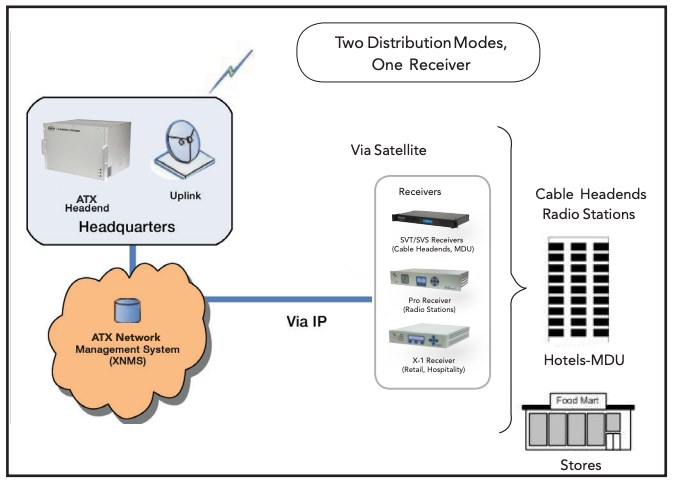
Xds Headend Application Diagram Atx Networks
Block diagram of the cable TV headend. Selecting a CATV station. Read more. Hybrid DVB & IPTV Headend. The solution from Crypton allows you to unify the same hardware and software modules in different devices of the headend of digital television. Block diagram of the cable headend and IPTV broadcasting.

Digital Headend Vois
Figure 10. Pilot Clock Connections Diagram - (4x4) Shared Rack Figure 11. Pilot Clock Connections Diagram - (4x4) Dedicated Rack 8. MANAGEMENT CONNECTIONS Notes: • One RJ45/RJ45 management cable is provided with each headend unit (i.e., HEU/OIU). • Management connections are also described in HCM quick installation sheet.

Block Diagram Of Cable Tv Network Electronics And Communication Study Materials
Introduction Of AES Encryption Algorithm. The AES Encryption Algorithm was approved in year 2000 and then it was published by NIST.NIST is National Institute Of Standards & Technology.. Although various algorithms was submitted by companies but Rijndael was selected. It was submitted by two cryptographers they were from Belgium named as Joan Daemen & Vincent Rijmen.

Switched Video Wikipedia
A.Work covered by this document includes design, engineering, labor, material and products, equipment warranty and system warranty, training and services for, and incidental to, the complete installation of new and fully operating National Fire Protection Association (NFPA) – Life Safety Code 101.3-2 (a) Labeled and (b) Listed, Emergency Service Nurse-Call and/or Life Safety listed Code Blue ...

Catv Provider To Subscriber Diagram 1 4 Cbg Communications
Crypton offers a full range of equipment of its own production for building a digital cable TV headend. Crypton adheres to the ideology of building a TV headend station from separate devices built into a standard 19inch rack. ... Block diagram of the cable TV headend. IP interface.

What S The Difference Between Cable And Dsl Broadband Access Electronic Design
- Cable - Leased line - Metro-optical 1.0 Networking Fundamentals Compare and contrast the Open Systems Interconnection (OSI) model layers and encapsulation concepts. Explain the characteristics of network topologies and network types. 1.1 1.2 CompTIA Network+ Certification Exam Objectives 3.0 (Exam Number: N10-008)
Is Aereo S Technology Really Like Cable Law And Entrepreneurship Blog Network University Of Notre Dame
Signal output from headend and details of distribution system: To determine the signal level required from the Headend system, a basic description of the distribution system is needed - info to include: layout of complex, number of outlets and representative cable run lengths. Click for Headend Diagram - Fig 1. 36 Channel MATV Headend System

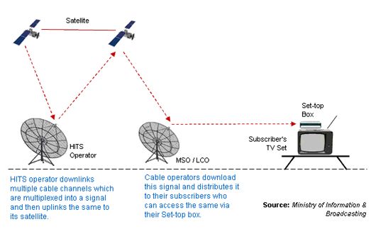
Hits Headends
In this diagram, there is a Cable Modem Termination System (CMTS) that consists of these ... document; refer to Connecting the Cisco uBR7200 Series Router to the Cable Headend for proper RF setup and measurements. Assumptions The upconverter is already installed and configured properly. Refer to the vendor's

Hybrid Fibrecoaxial Png Images Pngwing
Cable
Optical Amplifier Used In Catv Transmission Networkfiber Optic Components

Introduction To Cable Television 3rd Edition
Securing Networks In The Broadband Age Cablelabs

What Is Digital Headend Or Cable Tv Headend System
Regional Cable Head End Diagram Regional Cable Head End Diagram Draw Diagram Software Regional Cable Head End Diagram
Cable Internet Networkustad
The Challenges Of Monitoring Upstream Noise In A Remote Phy Environment
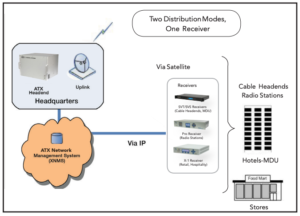
Xds Headend Application Diagram Atx Networks
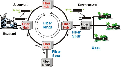
Hybrid Fiber Coax Hfc Access Network

Telecom Made Simple Cable Television Networks
16 In1 Catv Headend Modulatorr Adjacent Modulator For Hotel School Dormitory Rf Catv Modulator Modulator Modulator Catv Aliexpress

Introduction To Catv Two Way Cable Tv System
Cable Tv Systems 24 In 1 Analog Fixed Channel Modulator Headend Soukacatv Com By Soukacatv Issuu

Tutorial Deciphering Modem Signals Docsis Bob Is The Oil Guy

Sunsky


Comments
Post a Comment