39 aircraft wiring diagram
Contactors are used to switch high-current loads on the aircraft. Think of them as a big relay. A coil, when energized, creates a magnetic field and pulls the mechanical switch closed. The coil only draws a little bit of current, but allows you to switch very high-current loads like the starter. Figure 1 is a diagram showing a generic contactor. Electrical systems cessna aircraft system 172 nav iii by eric cannon listen closely tennessee services inc tip student pilot news brian brandi s rv 10 builder log sharing our files wiring diagrams mustang ii description and schematics model 172r 172s diagram 172rwd05 pdf voltage regulator harness power cables pilots of america chapter ppt online basic fuselage instruments source… Read More »
(FOD), lavatory fluid, and other contaminants produced by an aircraft environment from wiring systems. (c) Specify wire replacement guidelines when an accumulation of contaminants, either on the surface and/or imbedded in the wire bundle, cannot be safely ... the SWPM as chapter 20 of a wiring diagram manual, this reorganization would result in a
Aircraft wiring diagram
The proper bend radius for wire on aircraft should be 10 times the outside diameter of the largest diameter wire in the bundle for one side supported (3 times for two sides supported.) Standard industrial practice and is in AC 43.13-1b and Standard Wiring Practices Manual (SWPM). Aircraft Electrical Prints 14040 82. Aircraft Wiring Diagrams Advanced Course In 2020. Aircraft Electrical. Maintenance And Aircraft Mechanics Hot Air Balloon Aviation Training Hands Read. Read And Explain A Wiring Diagram Of Any Aircraft For You By Jeanphilippe Fiverr. Navy Electricity And Electronics Training Neets Module 3 11 Through 20 Rf Cafe. Electrical wiring diagrams are included in aircraft service manuals and specify information, such as the size of the wire and type of terminals to be used for a particular application. Wiring diagrams use for troubleshooting electrical malfunctions. Block diagram use as troubleshooting complex electrical and electronic systems. Pictorial diagram is a picture or sketch of the components of a ...
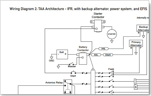
Aircraft wiring diagram. 91 CHARTS AND WIRING DIAGRAMS 3I4 91 CHARTS AND WIRING DIAGRAMS (CONT.) 4A17 PIPER AIRCRAFT PA - 2 8 - 1 8 1 AIRPLANE MAINTENANCE MANUAL Introduction Page 7 Reissued: July 30, 1994 1A7 Island Enterprises. 6-1. Three View - Archer II 1B20 6-2. Three View - Archer III 1B21 6-3. Station References - Archer II 1B22 Aviation drawings drawing symbols standardized wiring diagram color codes august 1956 por electronics rf cafe installation diagrams classroom poster electrical systems avotek legend maintenance and aircraft mechanics hot air balloon training handbooks read online basic of fuselage instruments power source system design matt s rv 7 project simplified part 2 by ron alexander prints typical ... aircraft wiring diagram s/n 2006 0810 page 1 of 5 . aircraft wiring diagram s/n 2006 0810 page 2 of 5 . aircraft wiring diagram s/n 2006 0810 page 3 of 5 ©2010 Vertical Power, Inc. "Top 10 Aircraft Wiring Mistakes" Page 2 B-lead. The B-lead is the big wire (typically a 6 or 8 gauge wire) that runs from the alternator to the bus. It carries the power generated by the alternator to the bus, which then distributes it to the individual devices and to the battery. An electrical bus
Aircraft Magneto Wiring Diagram. Aircraft magneto-ignition systems can be classified as either high-tension or low- tension. Figure shows a simplified schematic of a battery-ignition system. This is the job of the ignition system, be that the old fashion magneto of the good Mainly as you will still find these in the original and certified ... Aeroelectric Connection Aircraft Microphone Jack Wiring. Aviation Headset Connected To Ft 897 Flying N Stuff. Converting To 6 Pin Headset Connector General Mooney Talk Mooneye Com A Community For Aircraft Owners And Enthusiasts. Microphone David Clark Company Wiring Diagram Dc One X Headphones Png 930x604px Active. aircraft. • Location and directional dimensions are included. Block Diagrams • Used to simplify complex circuits • Shows the function and relationships of various components within a system. Schematics • Like block diagrams, they are used to explain a system. A wiring diagram is a simplified conventional pictorial representation of the physical connections and physical layout of an electrical system or circuit. Wiring diagrams show how the aircraft wires are connected and where they should be located in the electrical system, as well as the physical connections between all the components. This makes ...
insulation chosen for the aircraft, wire harness design engineer select wire part number to use. Using a 3D CAD system, the wire paths are specified throughout the aircraft. In addition, connector disconnects will determine when a wire goes through a bulkhead. Each wire in a wire segment is then uniquely identified (see Chapter 4 Wire Aircraft Wiring. Electrical system overview. By. Marc Ausman-June 19, 2015. 0. Electrical system overview. By Marc Ausman. To continue reading you must be a paid subscriber. Subscribe. Subscribe to Kitplanes. KITPLANES - The Independent Voice for Homebuilt Aviation KITPLANES® magazine is the world's #1 homebuilt aviation magazine. Written ... Overview Of Inspected Parts Pa34 220t Seneca V Aircraft View From Scientific Diagram. Piper Pa 23 Aircraft 31 Navajo 38 Tomahawk Propeller Png 1280x880px. Aircraft Cessna 172 150 Alternator Wiring Diagram Electrical Wires Cable Transport Png Pngegg. Piper Aircraft Pa 46 28 Cherokee 31t Cheyenne Electrical Wires Cable Airplane Png Pngegg. A wiring diagram is a simplified conventional pictorial representation of the physical connections and physical layout of an electrical system or circuit. Wiring diagrams show how the aircraft wires are connected and where they should be located in the electrical system, as well as the physical connections between all the components.
Awg
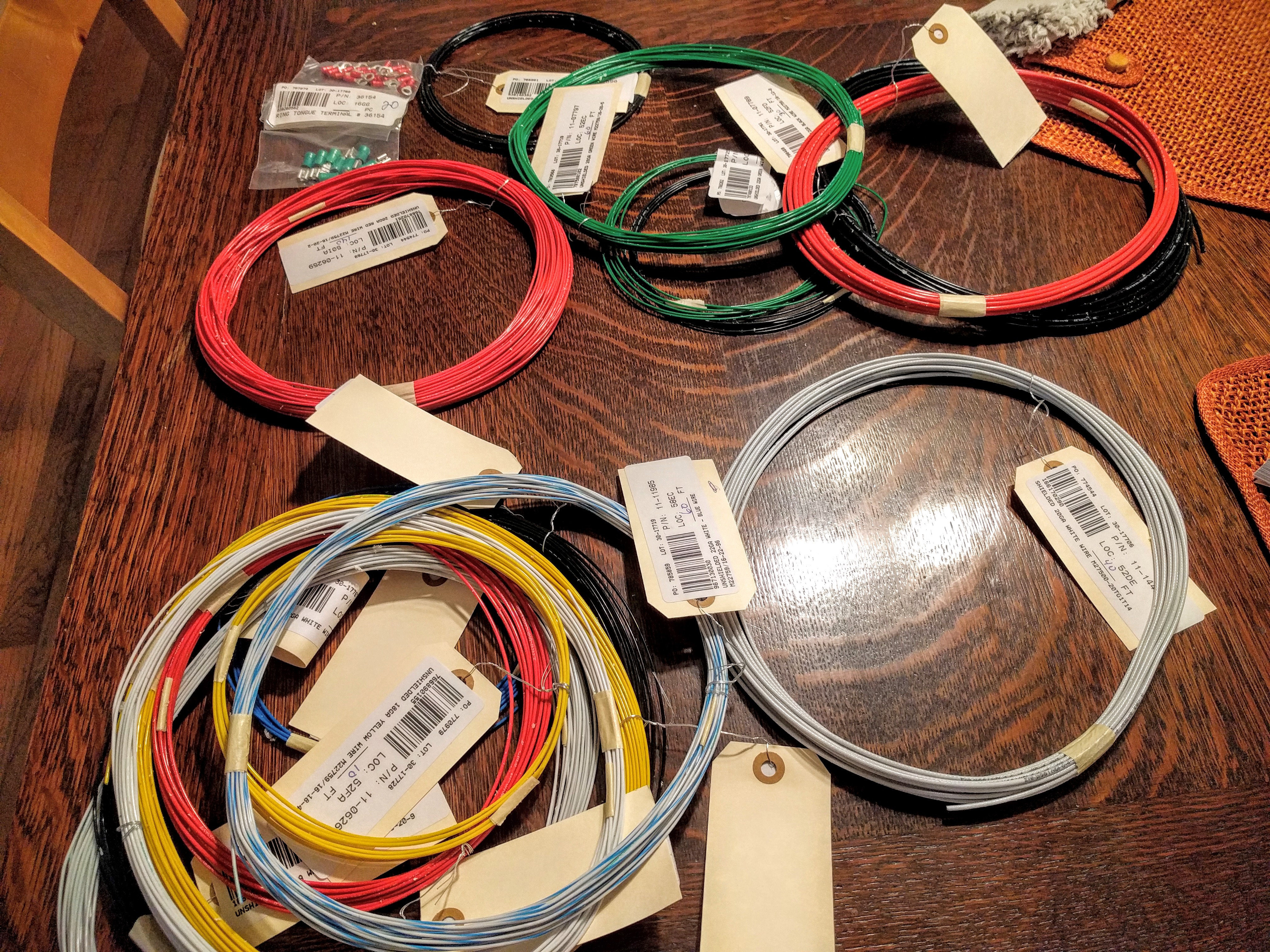
Early microlights were very simple aircraft with two -stroke engines and limited electrical systems . The obvious source for wiring components and crimp tools was the local car accessories shop. Early amateur-built aircraft such as Turbulents and Volksplanes were similarly basic.
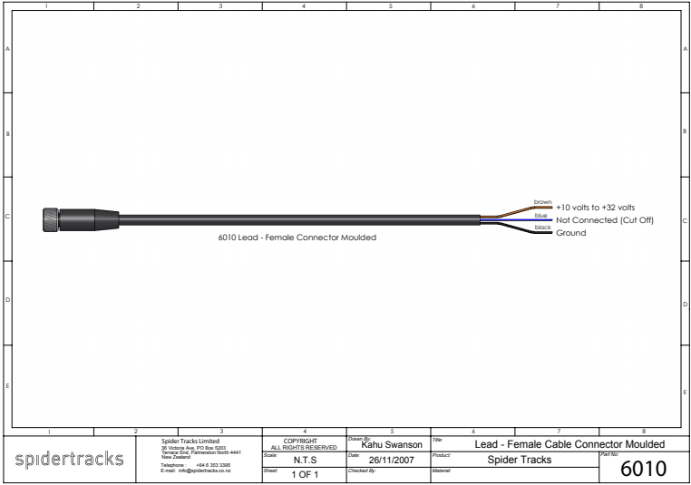
Power Lead Wiring Diagram Compatible With Spider 1 To Spider 8
Wiring diagram manual aircraft. Electrical wiring diagrams are included in aircraft service manuals and specify information such as the size of the wire and type of terminals to be used for a particular application. Wiring structural ipcaccessories manual and more. For details of the wiring the mechanic must use the wiring diagram manual.
3
C. Basic Aircraft Wiring This diagram shows a very basic aircraft system. All other systems would branch off this system. Basic Air craft Wiring Diagram Fig 27:C:1 Engine Battery L. Mag R. Mag Starter Starter Relay A Master Relay Alternator F1 B F2 Noise suppressor, Aircraft S pruce, 11-08060 Shielded wire Shielded wire Fuses 5 Amp Shunt Fuses ...

Aircraft Electrical Systems Small Single Engine Aircraft Part One
Aircraft wiring diagram software Electrical Systems. Word has a 'drawing' tool that can make line, circles, squares, etc. For major drawings, like Bob Nuckells', I copied them from pdf drawings using the photo copy tool (in the free Adobe reader), then used boxes of white to cover what I didn't want and added the lines I needed.
Airplane Wiring Diagrams Cheerful Curmudgeon
3 View's - All RV's: To download this zip file, Right Click on the file name, and save the "target/link" file to your local drive. 3_VIEW_ALL.zip 11.4 MB Compatible with AutoCAD R13, LT 95, or newer.. Instrument Panel Data Sets: To download these zipped DXF files, Right Click on the file name, and save the "target/link" file to your local drive.

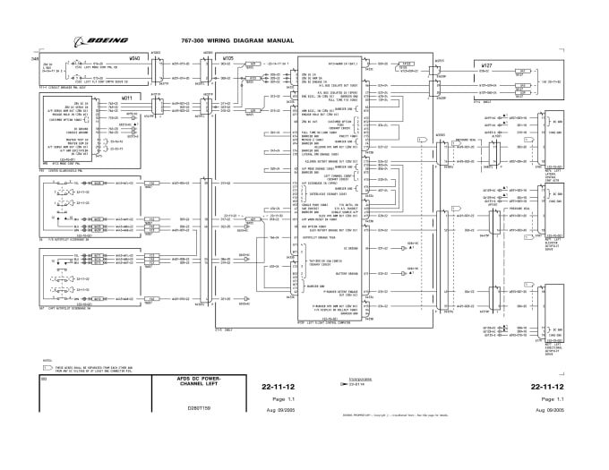
Diagram Based Boeing Aircraft Wiring Diagram Manual Wiring Diagrams And Wire Types Aircraft Electrical System
The first aircraft radios used carbon-granule microphones almost identical to microphones used on telephones. However, a second function was needed on the microphone in the form of a push-button to key the transmitter and effect a changeover from receive to talk . . . hence the name push-to-talk or PTT switch. ... Note that this wiring diagram ...
2
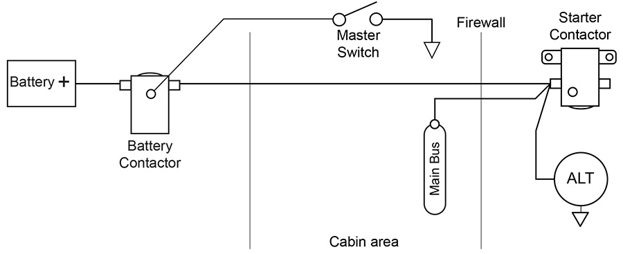
SCHEMATIC WIRING DIAGRAMS. The time proven way to work out an electrical system is with the help of a few free hand schematic sketches of the various circuits. These will enable you to get a better grasp on how the system will work, and what connects to what and where. Begin with a simple schematic diagram of the Alternator/Battery System.
2
Aircraft Wiring for Smart People ~ A Bare-Knuckles How-To Guide ~ 10 September 2004 Abstract This is a step-by-step, Foolproof 100% Gonna Work guide to wiring your airplane simply, effectively and inexpensively that builds on one basic principle: people who build
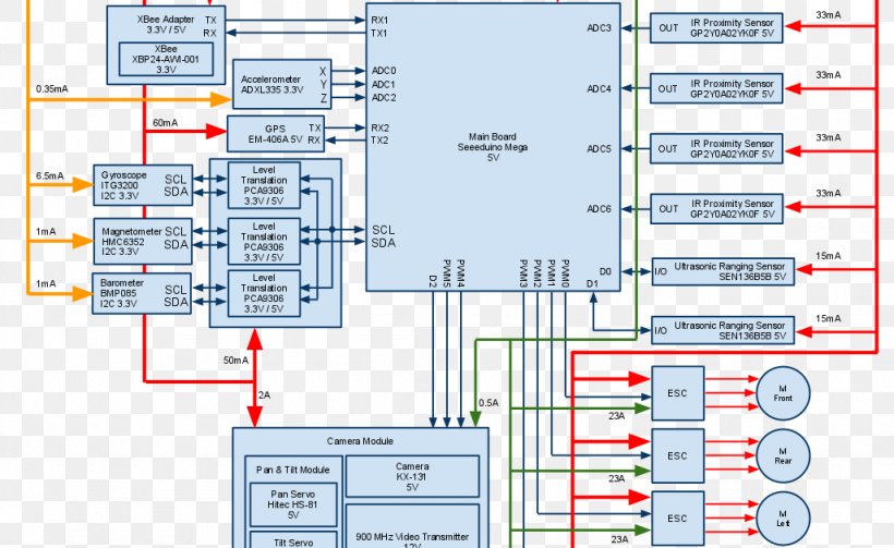
Fpv Quadcopter Wiring Diagram Unmanned Aerial Vehicle Png 1026x630px 3d Robotics Fpv Quadcopter Aircraft Flight Control
Wiring Diagrams. Such as the size of the wire and type of terminals to be used for a particular application. Furthermore, wiring diagrams typically identify each component within a. Including any changes that were made during the production run of an aircraft. Wiring diagrams are often used for troubleshooting electrical malfunctions.

Aircraft Wiring
Installation Instructions. Download the most current Installation Instructions for the following aircraft alternator models. FAMILY. MODEL NUMBER. MANUAL TYPE. .PDF. AL. AL12/24. Brush Block Replacement.
2
the basic concepts of Aircraft Wiring Practices, a course that provides an overview of the aging wiring history, an update on current FAA guidance, detailed information on AC 43.13-1b, AC 25-16, wire separation, and Instructions for Continued Airworthiness, and a review of what to look for on wiring diagrams and wiring installation drawings.

Data Captuare And Analysis System For Aircraft Wire Testing
Electrical wiring diagrams are included in aircraft service manuals and specify information, such as the size of the wire and type of terminals to be used for a particular application. Wiring diagrams use for troubleshooting electrical malfunctions. Block diagram use as troubleshooting complex electrical and electronic systems. Pictorial diagram is a picture or sketch of the components of a ...
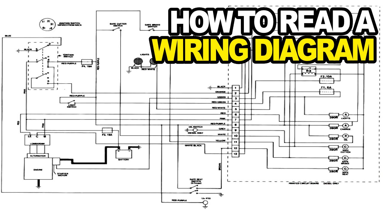
How To Read An Electrical Wiring Diagram Youtube
Aircraft Electrical Prints 14040 82. Aircraft Wiring Diagrams Advanced Course In 2020. Aircraft Electrical. Maintenance And Aircraft Mechanics Hot Air Balloon Aviation Training Hands Read. Read And Explain A Wiring Diagram Of Any Aircraft For You By Jeanphilippe Fiverr. Navy Electricity And Electronics Training Neets Module 3 11 Through 20 Rf Cafe.
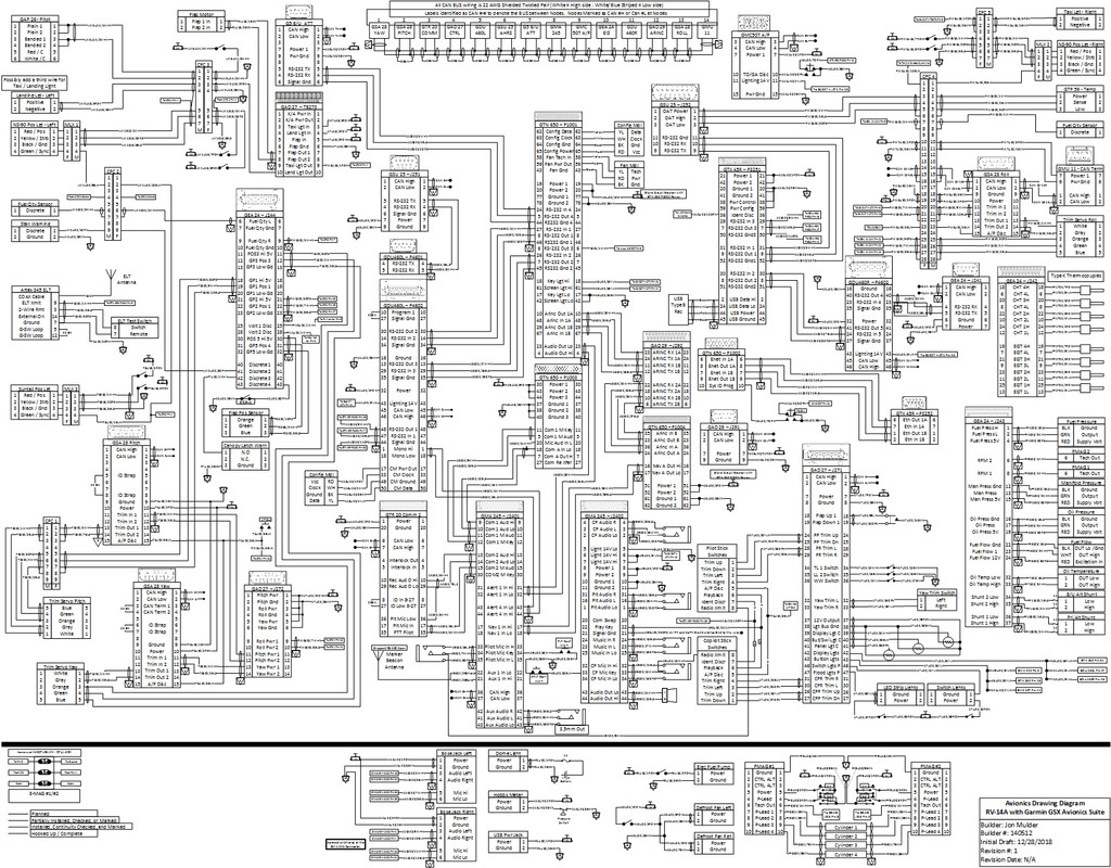
Rv 14 Electrical Diagram Vaf Forums
The proper bend radius for wire on aircraft should be 10 times the outside diameter of the largest diameter wire in the bundle for one side supported (3 times for two sides supported.) Standard industrial practice and is in AC 43.13-1b and Standard Wiring Practices Manual (SWPM).
Auxiliary Aircraft Systems
Ron Kilber S Logbook Aircraft Charging Systems
Aircraft Wiring
Developing Your Electrical System Part 1 Basic Preparation
2 3

Aircraft Electrical Prints 14040 82 Electrical Schematic Symbols Electrical Diagram Electricity
Read And Explain A Wiring Diagram Of Any Aircraft For You By Jeanphilippe Fiverr

Wiring Diagrams And Wire Types Aircraft Electrical System

Basics Of Aircraft Electrical Systems

Wiring Diagram 10 28 20 Kitfox Aircraft Build
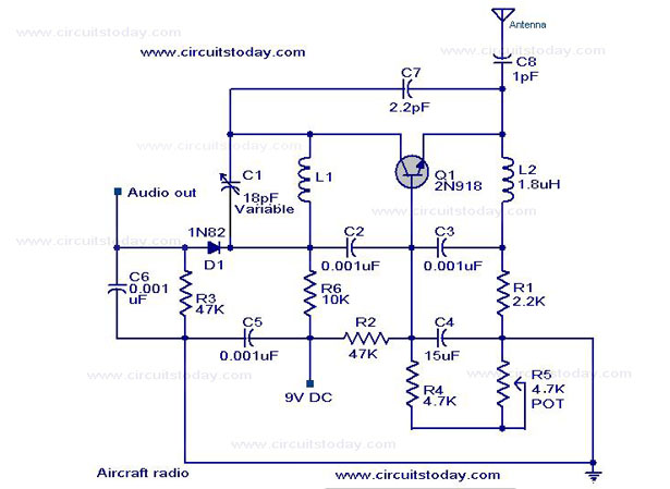
Simple Aircraft Radio Circuit Circuit Diagram Working

The Aircraft Electrical System An Overview Aerotoolbox

Developing Your Electrical System Part 3 Wiring Tips
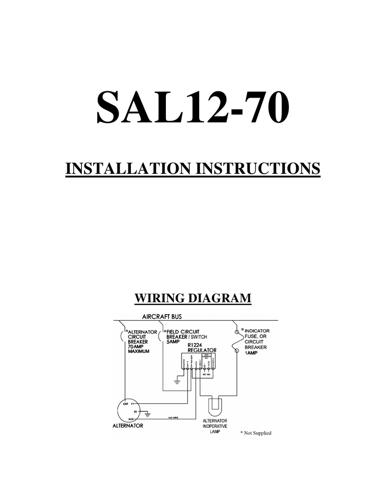
Installation Instructions Plane
3
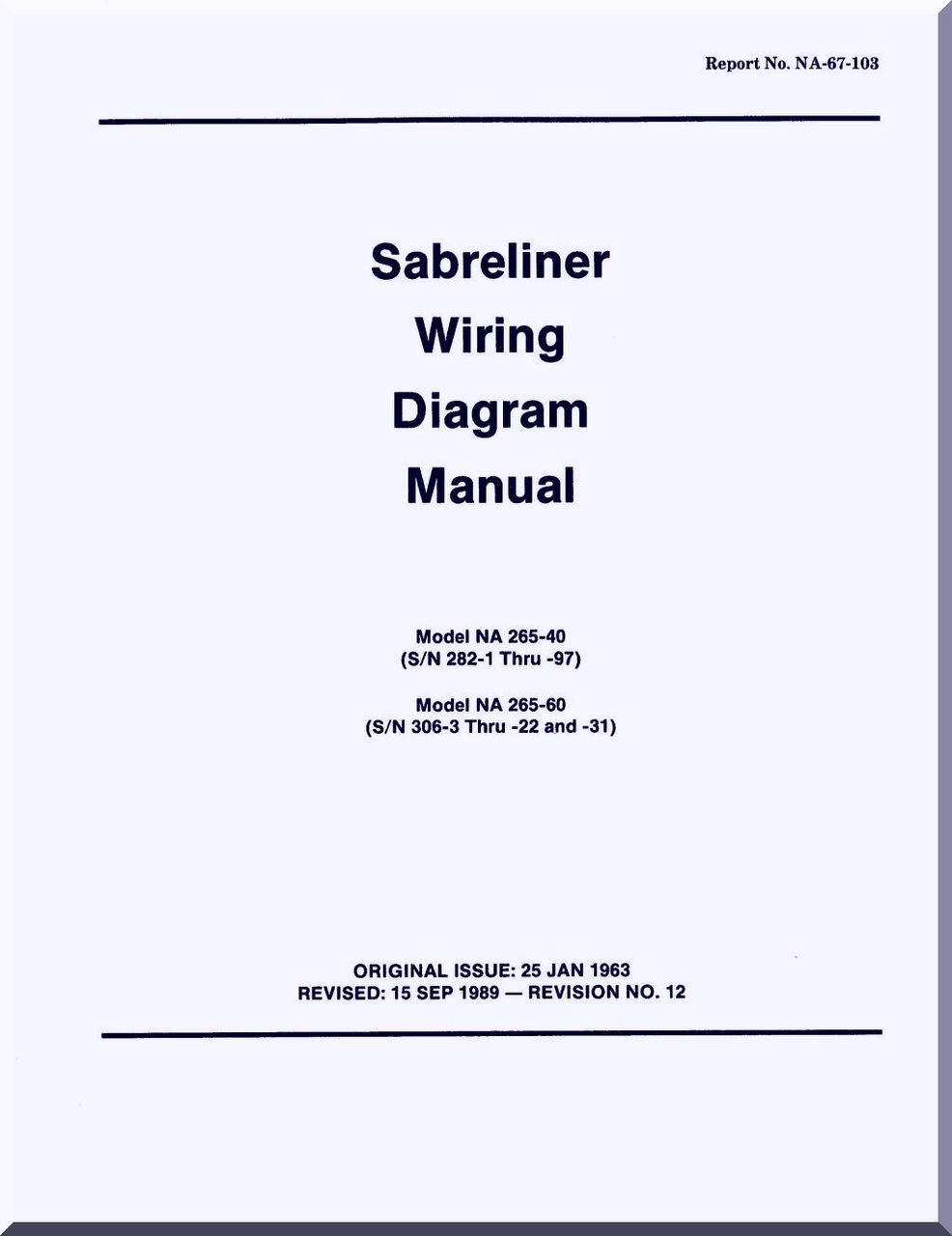
Sabreliner Na 265 40 60 Aircraft Wiring Diagram Manual Report No Na 67 103 1963 Aircraft Reports Aircraft Manuals Aircraft Helicopter Engines Propellers Blueprints Publications
Electrical System Design Matt S Rv 7 Project

Aircraft Generator Wiring Diagram New Toyota Fortuner Electrical Diagram Diagram Design Generator
Gulfstream Iii Aircraft Wiring Diagram Manual Aircraft Reports Aircraft Manuals Aircraft Helicopter Engines Propellers Blueprints Publications

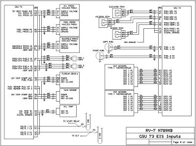
Wiring Diagram Of Mini Showtime Aircraft For Data Collection Download Scientific Diagram
Aircraft Wiring Diagrams Advanced Course In 2020

How It Works A Pilot S Guide To Magneto P Leads Aopa
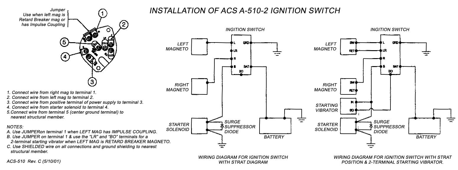
Acs Keyed Ignition Switch With Start Position A 510 2 Faa Pma Aircraft Spruce
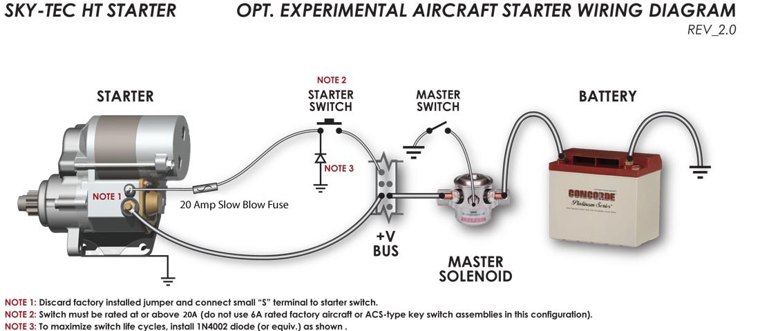
Experimental Wiring Diagram
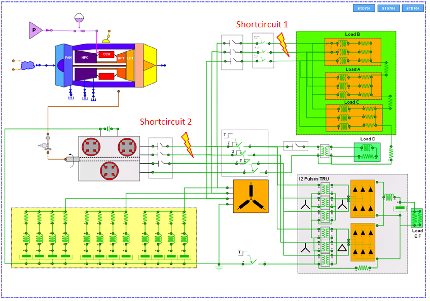
Electric Systems Aircraft Electric System Simulation


Comments
Post a Comment